background image

409-35011 


Rev D 

62 

of 83 

4.  In the 

Blade Guides

 field (Figure 73), select 

No Blade Guides Installed

Figure 73: Blade Guides field 


NOTE 

Blade Guides are for specific applications. Do not use them unless TE engineering recommended doing so. Contact TE 
Application Tooling Engineering for questions regarding Blade Guides. 

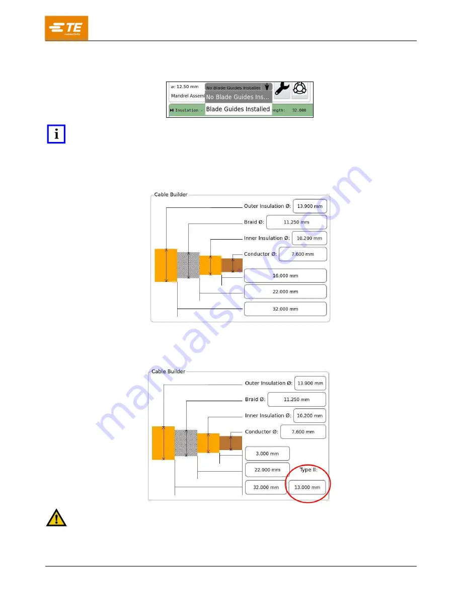
5.  In the Cable Builder, enter the cable layer diameters and strip lengths (Figure 74). 

Figure 74: Cable Builder for Process Type I 


If you selected Process Type II, the Cable Builder has an additional field where you can enter 
the Type II cut length (Figure 75). 

Figure 75: Cable Builder for Process Type II 


CAUTION 

To avoid damaging the braid, specify a Type II cut length that is 

less

 than the braid cut length. 

Summary of Contents for 2335400-1

Page 1: ...AD THIS FIRST 3 INTRODUCTION 4 SAFETY 5 Standards 5 Ear and eye protection 5 Safety covers and guards 6 Power connections 6 Safety interlocks 11 Emergency stop switch 14 DESCRIPTION 15 Machine overview 15 Specifications 17 Major components 18 RECEIVING INSPECTION AND INSTALLATION 28 Receiving inspection 28 Installation 34 OPERATION 39 Overview 39 User interface 40 Initial startup 59 Processing 59 ...

Page 2: ... flammable liquids could ignite and cause serious injury or property damage Failure to heed these warnings could result in severe injury from harmful fumes or burns from flying debris DANGER Inspect the tool and jaws dies before each use Replace any worn or damaged parts A damaged or improperly assembled tool can break and strike nearby personnel Failure to observe this warning could result in sev...

Page 3: ...quipment if the guards are removed Read and understand this entire document before using equipment CALL TOLL FREE 1 800 522 6752 CONTINENTAL UNITED STATES AND PUERTO RICO ONLY Canada 1 800 522 6752 China 86 400 820 6015 Mexico 52 55 1106 0800 Latin South America 54 11 4733 2200 Germany 49 6151 607 1999 UK 44 0800 267666 France 33 1 34 20 8686 Netherlands 31 73 624 6999 The Support Center offers a ...

Page 4: ...nt INTRODUCTION This manual contains the safety installation setup operation and maintenance procedures for the TE Connectivity High Voltage Cable Preparation HV CP machine part number 2335400 1 Figure 1 Throughout this manual the left right and front side of the machine are defined as shown in Figure 1 ...

Page 5: ...t in product or equipment damage NOTE Highlights special or important information Standards The HV CP machine is designed to comply with the following standards European Machinery Directive 2006 42 EC European EMC Directive 2014 30 EU Ear and eye protection Always wear approved eye and ear protection while operating equipment The following applies to the sound level produced by the HV CP machine T...

Page 6: ...sed before operating the machine Power connections Main electrical power disconnect The main electrical power disconnect switch is located on the left side of the machine Figure 3 Figure 3 Main electrical power disconnect switch DANGER Never enter the electrical enclosure immediately after turning OFF the machine power switch and disconnecting the electrical power source High voltage electrical en...

Page 7: ...serting a padlock not included into the locking locations Figure 4 Locking out electrical power d 4 8 mm 0 16 0 31 in b 47 mm 1 85 in CAUTION Always turn off the main power switch and disconnect the electrical cord from the power source when performing repair or maintenance on the equipment Lock out electrical power when performing maintenance or repair on this equipment ...

Page 8: ...h The main air valve will exhaust all residual air from the machine when turned from the Supply SUP position Figure 5 to the Exhaust EXH position Figure 6 Figure 5 Main air disconnect valve in SUP position DANGER Moving parts can crush and cut Lock out air supply when performing maintenance or repair on this equipment Lock out electrical power when performing maintenance or repair on this equipmen...

Page 9: ...the EXH position Lock Out Tag Out for maintenance or repair by inserting a padlock not included into the locking location Figure 6 Figure 6 Main air disconnect valve in EXH position 1 Indicator shows EXH position 2 Install Lock Out Tag Out padlock here ...

Page 10: ...ent the cable from slipping in the gripper jaws Figure 7 It also allows the cable grip to be released if the guard door is opened and the red button on top of the airlock valve is pressed The airlock valve is located inside the machine s sliding door to the left of the gripper jaws Figure 7 CAUTION The system might be pressurized Figure 7 Airlock valve and gripper jaws 1 Airlock valve 2 Gripper ja...

Page 11: ...STO function In this state the drives are still energized but their motor outputs are disabled the machine air supply is turned OFF and residual air pressure is exhausted This effectively stops all machine motion When the sliding door is closed and if the Emergency Stop relay is energized the Interlock safety relay automatically re enables the STO outputs and reapplies air pressure CAUTION The mac...

Page 12: ...409 35011 Rev D 12 of 83 Figure 9 Top guard interlock open ...

Page 13: ...gure 10 disables the vacuum system It does not disable the servos or drop the air pressure CAUTION Do not open or empty the scrap bin while a cable prep cycle is in progress NOTE Resetting an interlock does not automatically restart the machine Figure 10 Scrap door safety interlock open ...

Page 14: ...TO function The drives remain powered up but their motor outputs are disabled The air pressure is evacuated This effectively stops all machine motion The E STOP switch is monitored by an independently dedicated safety relay When pressed the E STOP switch latches in the pressed state In order to continue using the machine you must reset the Emergency Stop safety relay 1 Close the sliding door and t...

Page 15: ... touchscreen display assists the operator with setting the processing parameters by creating an article building a cable profile setting the run parameters and initiating a production run Integrated air jets for automatic blade cleaning and an in line vacuum to remove slugs keep the processing area clean and efficient A removable container is located inside the chassis for easy waste disposal Spec...

Page 16: ... 16 of 83 Labeling A label on the left side of the machine Figure 12 provides the machine part number serial number manufacture date and electrical specifications Figure 13 Figure 12 Location of label Figure 13 Label ...

Page 17: ...preferred machine working pressure 0 69 MPa 100 psi Max supply line pressure 0 83 MPa 120 psi Ambient temperature for operation 5 40 deg C non condensing Table 3 Physical characteristics Width 690 mm Height 1500 mm Depth 1000 mm Weight 238 kg 524 lbs NOTE A customer supplied 3 conductor power cord 14 AWG approx 2 mm2 is required for the L1 L2 and PE connections See section 4 2 for directions for c...

Page 18: ... tightening the knobs Sliding Door The sliding door Figure 14 is the main guard for the mechanisms of the machine The door has a catch at the top of its range allowing for the door to be held open for the transfer of short cables and tooling changeovers NOTE During the machine cycle this door must remain fully closed If the door is opened during a cycle the cycle stops This can result in a defecti...

Page 19: ...he cable is securely held In response to the process parameters the gripper moves the end of the cable to the correct location with respect to the blades and rollers Figure 16 CAUTION The gripper moves inward and outward from the machine during the cycle which causes longer cables to move This also moves the cable tunnel that extends outside of the machine Figure 15 Gripper jaws Figure 16 Gripper ...

Page 20: ...rogram Contour blades Three contour blades are used for cutting the insulation and foil layers of the cable Each blade set is designed for a specific cable size see Table 4 for tooling specifications The blades are connected to the cutting arms by a pin and machine screw for easy changeover Cutting wheels Three cutting wheels are used for opening and cutting the braid The same wheel set can be use...

Page 21: ...s the head rotates around the mandrel The mandrel is a wear item The machine warns the user when the mandrel is nearing the end of its life expectancy This is determined by the braid cut depth when it reaches its maximum allowable value The machine does not allow a user to use a mandrel past this allowable value preventing the mandrel from breaking during operation Figure 18 Mandrel Cable sensor W...

Page 22: ...end of the cable to the cable sensor It consists of top and bottom portions to direct the cable end fully Figure 20 The cable tunnel s top portion hinges open Figure 21 to allow shorter leads to be placed When using the cable tunnel in this manner operate the machine with Auto Start turned off Figure 20 Cable tunnel closed Figure 21 Cable tunnel open ...

Page 23: ...erator when the scrap bin is nearing maximum capacity This alert changes the Trash Full status indicator to red and displays a warning that the SCRAP BIN IS NEARLY FULL In order to complete a batch or reach a convenient time to halt production the operator can select OK to return to the production screen and continue production for up to 50 cycles During this time the status indicator remains red ...

Page 24: ... logic controllers safety relays etc for controlling the machine DANGER The electrical enclosure contains no user serviceable parts Do not open the door Opening this door always presents the danger of electrical shock and must be performed only by qualified personnel Call field service for assistance Figure 24 Electrical enclosure 1 Panels 2 Electrical enclosure ...

Page 25: ... switch to the ON position supplies AC power to the machine Turning the switch to the OFF position disconnects the incoming AC power It can be locked in the OFF position for safety and security proposes Main pneumatic disconnect Provides oil free and water free air for machine operation This assembly contains a pneumatic lock out valve and a digital pressure switch NOTE The digital pressure switch...

Page 26: ... NOTE Contact Application Tooling engineering for details regarding implementation of an MQTT message reader Tooling Instructions for a tooling changeover different cable or tooling replacement worn or broken tooling are presented in section 6 3 Cutting wheels contour blades and mandrels are wear items Order several sets of tooling and keep them on hand at all times Use Figure 27 to understand how...

Page 27: ...0 1 15 8 0 6 12 1 0 7 12 09 12 20 10 5 2360456 5 2364113 5 60 0 16 9 0 6 13 0 1 2 12 99 13 30 11 6 2360456 6 2364113 6 70 00 18 2 0 8 14 4 1 4 12 5 2360456 7 2364113 7 95 000 20 9 0 8 17 2 1 4 14 8 2360456 8 2364113 8 120 0000 23 0 0 8 19 0 1 4 16 5 2360456 9 2364113 9 NOTE Table 4 lists the correct tooling needed for each cable size The manual override column only applies to two of these sizes Du...

Page 28: ...ts and inspections are made to ensure proper functioning 1 After the machine is received at the facility of use compare it to Figure 28 Make note of any differences If tooling blades mandrels etc are shipped separately they must be inspected separately Examine the Tip N Tells and photograph them if they indicate tipping or mishandling during shipment Figure 28 How a newly received HV CP should loo...

Page 29: ...re it will be used NOTE Lift from the bottom of the machine Keep forks spread as wide as possible for better stability 7 Remove the foam hat PN 2358910 or bubble wrap protecting the monitor Figure 29 Figure 29 Removing the foam hat 8 Remove the corrugated cardboard inserts securing the scrap bin Figure 30 DANGER To prevent static shock the cardboard inserts must be removed before operation The scr...

Page 30: ... tie wraps from the door weights on the left side Figure 31 and the right side Figure 32 Figure 31 Left door weight Figure 32 Right door weight 10 Remove the tie wraps holding the top guard in place Figure 33 Figure 33 Top guard tie wraps ...

Page 31: ...g a pin to one of the cutting arms Figure 34 Figure 34 Plate securing a pin to one of the cutting arms 12 Remove the tie wrap holding the wire pull actuator in place Figure 35 and Figure 36 Figure 35 Cable tunnel top view Figure 36 Cable tunnel side view ...

Page 32: ...in a safe location 14 Remove the tie wrap holding the main air disconnect valve in the EXH position Figure 37 Figure 37 Electrical enclosure key and main air disconnect valve 1 Main air disconnect valve 2 Electrical enclosure key 15 Remove the tie wrap holding the gripper jaws together Figure 38 Figure 38 Gripper jaws ...

Page 33: ...s Figure 39 and Figure 40 Figure 39 Left cable gate cylinder Figure 40 Right cable gate cylinder 17 Verify that all components are secure 18 Check all wiring for loose connections frayed or broken wires and damaged insulation 19 Verify that all components and parts listed in the Bill of Lading are accounted for ...

Page 34: ...rial air line and connect it to the machine port The final connection should resemble Figure 41 NOTE The digital pressure switch and the air regulator are set at the factory Do not modify their settings Figure 41 Connecting the pneumatic supply 1 Pneumatic lockout valve 2 Main supply port 3 Quick disconnect customer supplied 4 Air line customer supplied 5 Machine air regulator 6 Digital pressure s...

Page 35: ... disconnect install a customer supplied three conductor power cord rated for the supply voltage and current capacity Before connecting the power cord you must disassemble the main disconnect Figure 42 Figure 42 Main power disconnect switch ...

Page 36: ...ve the dial c Remove the two faceplate screws d Remove the faceplate e Remove the two cover screws f Remove the cover Figure 43 Disassembling the disconnect enclosure 1 Dial screw 0 6 Nm 5 31 lb in 2 Faceplate screws x2 ST 3 9 x 19 1 Nm 8 85 lb in 3 Cover screws x2 1 2 Nm 10 62 lb in 4 Cover 5 Faceplate 6 Dial ...

Page 37: ...cord through the cable gland at the bottom of the disconnect enclosure Figure 44 8 Connect line conductors to main disconnect switch terminals Figure 44 Figure 44 Interior of disconnect enclosure 1 L1 2 N or L2 3 Ground 4 Power cord cable gland ...

Page 38: ... D 38 of 83 9 After installing the power cord Figure 45 tighten the cable gland to secure the cord Figure 45 Disconnect enclosure with power cord installed 10 Reassemble the disconnect enclosure by reversing step 6 ...

Page 39: ... end contacts the auto sensor If Auto Start is enabled the cycle initiates when the cable contacts the sensor If Auto Start is not enabled the operator must press the manual cycle start button to start the cycle CAUTION Verify that the cable size you are using matches the article on the machine Using the wrong size cable can result in damage to tooling machine and cable 2 The cable grip jaws close...

Page 40: ...olbar in the UI touch the menu expand collapse arrow Figure 46 Touch the arrow again to collapse the toolbar Figure 46 Production screen 1 Menu expand collapse arrow 2 Manual cycle start button Touch the Back Arrow button to return to the previous screen Touch the Home button to display the Production screen The Help button is not used with this model Touch the Control Panel button to display the ...

Page 41: ... following steps 1 On the control panel touch the language icon The language dialog is displayed Figure 49 Figure 49 Selecting a language 2 Touch the down arrow button to the right of the language field A list of available languages is displayed 3 Touch the language you want to use 4 If you want the selected language to be automatically selected when the unit powers ON touch the Set as Default but...

Page 42: ... Figure 50 Figure 50 Setting the time 2 Use the up and down arrow buttons Figure 50 to set the time 3 Touch the SET button to save 4 To change the date touch the Date tab The calendar is displayed Figure 51 Figure 51 Setting the date 5 Change the month day and year to the correct value 6 Touch the SET button to save ...

Page 43: ...3 of 83 7 To set the time zone touch the Time Zone tab The time zone is displayed Figure 52 Figure 52 Setting the time zone 8 Touch the drop down arrow and select a time zone from the menu 9 Touch the SET button to save ...

Page 44: ...Control Panel Figure 48 Figure 53 Users screen 1 Add New User button 2 Down arrow button 3 Change Password button 4 Delete button 5 Permissions buttons 1 In the upper left corner touch the Add New User button A new user form is displayed Figure 54 Figure 54 New user form 2 Enter the username 3 Enter the password 4 Verify the password by entering it again ...

Page 45: ...g Operator can Article Change articles Article Approval Not used with model Turn this permission off for all users Article Data Access new copy delete process type Cable Data Import and modify cables for example cable layer diameters and strip lengths Data Backup Import Back up or import articles with a USB flash drive Date Time Change the date time and time zone Diagnostics Access the Diagnostics...

Page 46: ...rmissions as Operator A plus Switch between articles of the same cable size Change Strip Type Operator C Article Strip Type Tooling Change Same permissions as Operator B plus Switch between articles of different cable sizes Operator D Article Article Data Cable Data Data Backup Import Setup Mode Strip Type Tooling Change Same permissions as Operator C plus Create modify import and back up articles...

Page 47: ... and Network icons 1 The Network page is displayed with the Configuration tab selected 2 Touch the Status tab An IP address is displayed Record this address 3 Navigate back to the Control Panel Figure 56 IP address on Status tab 4 On the Control Panel touch the Remote Support icon Figure 55 A page with a Remote Support button in the center is displayed 5 Touch the Remote Support button 6 Give the ...

Page 48: ...s Table 7 Locale settings Setting Description Thousands separator Selects the character displayed between groups of digits in large numbers Decimal symbol Selects the character displayed between the ones digit and the tenths digit Time format Selects the format used to display times Date format Selects the format used to display times Units Two radio buttons select whether metric or imperial units...

Page 49: ...o a USB flash drive as text files see Exporting version information on page 51 Firmware Update Used by TE field service for updating the firmware Reset Zero Used to reset the zero positions for the blades gripper and mandrel see Resetting zero positions on page 52 Life Cycle Used for initial machine setup For life cycling the machine enter in the number of dry cycles you would like the machine to ...

Page 50: ... a USB flash drive The Version and Article Database tabs require the use of a USB flash drive To use these features insert the flash drive into one of the USB ports located in the utility alcove Figure 59 Figure 59 Location of USB ports ...

Page 51: ...rts see Inserting a USB flash drive on page 50 2 On the Control Panel touch the Maintenance icon The Maintenance screen is displayed with the About tab selected 3 Touch the Version tab The Version controls are displayed Figure 60 4 Touch the Save to File button at the bottom The version information is exported to the flash drive as text files Figure 60 Version tab ...

Page 52: ... of 83 Resetting zero positions This tab has buttons that reset the zero positions for the blades gripper and mandrel Figure 61 Touch the appropriate button and follow the on screen instructions Figure 61 Reset Zero tab ...

Page 53: ...1 Rev D 53 of 83 The tooling change tool Figure 62 is required for the Reset Zero process Insert the pin into the calibration hole Figure 63 Figure 62 Tooling change tool PN 2361560 1 Figure 63 Calibration hole ...

Page 54: ...ash drives allowing for quick transfer of programs from machine to machine Exporting an article To export an article complete the following steps 5 Insert a flash drive into one of the USB ports see Inserting a USB flash drive on page 50 6 On the Control Panel touch the Maintenance icon The Maintenance screen is displayed with the About tab selected 7 Touch the Article Database tab The Article Dat...

Page 55: ...button To select a single article a Touch the down arrow icon to the right of the Article field A list of articles is displayed b Touch the article you want to export c Touch the Backup Article button The export controls are displayed Figure 65 Figure 65 Export controls 9 Touch the USB button 10 Touch the File Name field ...

Page 56: ... shown in Figure 66 If you save to the same file more than once on the same day the existing file is overwritten To avoid this enter a different filename Figure 66 Entering the filename 12 Touch the Save button The article data is exported A message confirms that the export is completed 13 At the top of the screen touch the Eject button A message confirms that the flash drive has been ejected and ...

Page 57: ...igure 67 Import controls 3 Touch the USB button A list of the JSON files on the flash drive is shown 4 If you are importing a single article select the JSON file for that article CAUTION If the machine already has an article with the same name as the one you are importing the existing article is overwritten and cannot be recovered 14 Touch the Load button The article data is imported A message con...

Page 58: ...e Login Logout screen The user that is logged on will be displayed 2 Choose Logout to select a new user 3 Choose the new user from the dropdown list 4 Enter the password for that user If no password is selected none is needed to Login Logout of the system NOTE The system initially has only a single User the Administrator and no password is required After other users are added or a password is ente...

Page 59: ...machine does not run if the pressure value on the pneumatic pressure switch is too high or too low Refer to Table 2 for the correct pressure Logging in To log into the machine complete the following steps 1 On the Control Panel Figure 48 select Login Logout A login dialog is displayed Figure 68 Figure 68 Login dialog 2 Touch the menu button and select the appropriate user name 3 Enter the password...

Page 60: ...ady for production use Figure 69 Article dialog 1 New article button 2 Copy article button 3 Delete article button 4 Menu button Creating an article A user must have Operator D permissions see Table 6 to create an article You can create an article by specifying all the parameters or by copying an existing article and changing only the parameters that are different Figure 70 Creating an article 1 I...

Page 61: ... cut in a sacrificial portion of the braid ensuring that the foil is completely cut through This enables the machine to more easily flare the braid in the next step to prepare it for cutting 4 In the Import field select a type of cable Figure 71 This value determines the type of cable that is displayed in the Cable Builder Figure 71 Selecting the cable type Use 0 2 LAYER for single insulation sing...

Page 62: ...Tooling Engineering for questions regarding Blade Guides 5 In the Cable Builder enter the cable layer diameters and strip lengths Figure 74 Figure 74 Cable Builder for Process Type I If you selected Process Type II the Cable Builder has an additional field where you can enter the Type II cut length Figure 75 Figure 75 Cable Builder for Process Type II CAUTION To avoid damaging the braid specify a ...

Page 63: ...final braid length greater than 7 mm increases the mandrel wear life Figure 76 Entering the strip length 7 The Mandrel Assembly field is automatically populated with the appropriate mandrel kit based on the cable diameters listed in the Cable Builder In some cases this kit can be changed if the diameters are within the range of the manual override diameters see Table 4 Touch the menu button Figure...

Page 64: ...erator D level permissions see Table 6 to adjust an article 1 On the right side of the Production screen in the Operational Mode box touch the radio button to select Setup Mode Figure 78 Figure 78 Operational Mode buttons 2 On the left side in the Process Step box Figure 79 touch the process step you want to adjust Figure 79 Process steps ...

Page 65: ...djustment verification will need to be performed to ensure the parameters have not changed to continue with the production run of the article Verification is automatic and status is displayed on the production screen NOTE You can adjust the strip lengths by editing the fields in the Cable Builder Figure 74 and Figure 75 NOTE Insulation Type II Coarse Cut Insulation Coarse Cut outer insulation and ...

Page 66: ...e II Coarse Cut The advanced settings for Insulation Type II Coarse Cut are listed in Table 10 These settings all relate to the current diameter which is controlled by the Settings for each process step Figure 80 Table 10 Advanced settings for Insulation Type II Coarse Cut Setting Description Speed The speed at which the cutting arms rotate around the cable Rotations at cut diameter The number of ...

Page 67: ...This unique cutting motion prevents the countour blades from damaging conductor strands Degrees Rotation The angle distance between chops Insulation Wayback Figure 83 shows the advanced settings for Insulation Wayback Figure 83 Advanced settings for Insulation Wayback The advanced settings for Insulation Wayback are listed in Table 12 These settings all relate to the current diameter which is cont...

Page 68: ...f times the cutting wheels rotate at the current diameter Gripper move The amount the gripper translates during the flaring operation Braid Cut Figure 85 shows the advanced settings for Braid Cut Figure 85 Advanced settings for Braid Cut The advanced settings for Braid Cut are listed in Table 14 These settings all relate to the current diameter which is controlled by the Settings for each process ...

Page 69: ...m duration The amount of time that the vacuum is turned on Increase this value if scrap pieces are larger Partial Pull Figure 87 shows the advanced settings for Partial Pull Under the final Insulation Wayback Advanced Settings operators can select Partial Pull by touching the radio button Figure 87 When Partial Pull is selected the inner insulation is cut at the inner insulation strip length and r...

Page 70: ...achine Status areas Figure 88 provide individual status indicators for key functions of the machine and the article If all functions are in good standing all indicators are green and the circular indicators are filled for Valid and Ready The indicators for Article Status ensure that the machine is capable of processing that article with the current settings The machine status indicators ensure tha...

Page 71: ...e debris Inspect contour blades for nicks gouges or burrs Blades must be changed between different cable types and after a certain amount of usage For contour blade removal and replacement refer to section 6 3 C DANGER Contour blades are extremely sharp Handle with caution Inspect cutting wheels for nicks gouges or burrs Wheels must be changed after a significant amount of usage but not between di...

Page 72: ...ER Tightening or loosening bolts on the face of the pulleys can cause the mechanism to move Be careful where you place your hands when changing tooling Complete the Lock Out Tag Out procedure before you begin the tooling changeover Changeover tooling is stored in the tooling holder which is located inside the machine behind the scrap door Figure 90 Figure 90 Location of tooling holder ...

Page 73: ...paring the machine for tooling changeover 1 Touch the Tool Change button Figure 92 The machine retracts the wire clamp and cable sensor The mandrel moves forward to its farthest outward position Figure 92 Tool change button 2 Rotate the main power switch to the OFF position as shown in Figure 4 and lock it there by inserting a padlock into the locking locations ...

Page 74: ...ut Tag Out procedure steps 2 and 3 before you begin the tooling changeover Removing a quick change arm assembly 4 Prepare the machine see Preparing the machine for tooling changeover on page 73 5 Rotate one of the quick change arm assemblies clockwise until the installed contour blades are clear of the other arm assemblies Figure 93 Figure 93 Rotating a quick change arm assembly ...

Page 75: ...75 of 83 6 With one hand grasp the locking slide Figure 94 and pull it away from the pivot pin Figure 95 Figure 94 Quick change arm assembly 1 Locking slide 2 Cutting arm 3 Pivot pin Figure 95 Pulling the locking slide ...

Page 76: ...ne see Preparing the machine for tooling changeover on page 73 2 Remove the quick change arm assembly from the machine see Removing a quick change arm assembly on page 74 3 While holding the cutting arm in place to prevent rotation use a 3 mm hex head wrench to loosen the M4 socket head cap screw Figure 97 Do not remove the screw Figure 97 Removing the contour blade 1 Dowel pins 2 Contour blade 3 ...

Page 77: ...on page 74 3 Using a 3 mm hex head wrench remove the M4 socket head cap screw that holds the cutting arm cap in place Figure 98 Figure 98 Parts of the quick change arm assembly 1 Cutting wheel 2 Cutting arm cap 3 M4 socket head screw 4 Remove the cutting wheel assembly taking note of the wheel orientation 5 Place the new cutting wheel assembly onto the cutting arm cap in the correct orientation NO...

Page 78: ...u will feel engagement as the wings of the tool go into the slots in the machine Figure 100 Mandrel DANGER The mandrel tip and contour blades represent dangerous cut and puncture hazards Use extreme caution when working in their vicinity 4 Turn the tool counterclockwise to loosen the mandrel 5 Carefully remove the mandrel 6 Place the new mandrel into the changeover tool 7 Insert the tool and mandr...

Page 79: ... proper tooling set for the application is installed Figure 101 Calibration button 5 Dispose of removed parts in compliance with the standards in force in the country where the tool is used Tooling changeover for 50 60 mm2 size cables Due to the variance in the cable diameters the machine selects the most appropriate tooling for the diameters provided However you can select another set of tooling ...

Page 80: ...hape Cable not straight enough not touching sensor Remove cable and restraighten Re insert cable and point any bend upwards if possible Gravity will help straighten the cable Scrap tube clog Bin full or an obstruction in tube Empty bin or clear obstruction from the scrap tube by removing the bin and clearing the scrap above Misshapen or poor cuts Dull tooling Replace tooling Improper cut Rotary he...

Page 81: ... You can also order parts by any of the following methods Go to TE com and click the Shop TE link at the top of the page Call 800 522 6752 Write to CUSTOMER SERVICE 038 035 TE CONNECTIVITY CORPORATION PO BOX 3608 HARRISBURG PA 17105 3608 For customer repair services call 800 522 6752 Table 17 Customer replaceable parts Part number Description Number per assembly 2079454 1 Sensor 5 2030531 1 Sensor...

Page 82: ...ct the sensor from the main wiring harness by unscrewing the M8 connector at the end of the sensor wire Remove the top rear cover to gain access to the end of the sensor wire if necessary 2 Use a small screwdriver to loosen the sensor mounting screw 3 Slide the sensor out of the slot in the actuator 4 Install and connect the new sensor 5 Re install the top rear cover if removed 6 Connect power and...

Page 83: ...ed the user must make sure that waste produced during operation is correctly disposed Disposal of lubricants and removed parts must be carried out in compliance with the standards in force in the country where the tool is used REVISION SUMMARY Converted to standard Customer Manual format Reorganized and edited to improve clarity Added new information about calculating braid length see step 6 on pa...

Reviews: