409-35011
Rev D
65
of 83
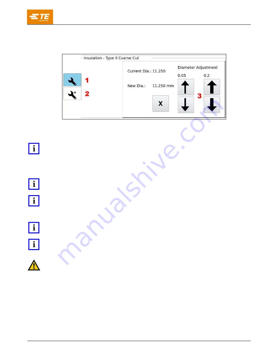
3. On the right side, use the up and down Diameter Adjustment arrows (Figure 80) to set the blade
and cutting wheel depths.
Figure 80: Standard settings
1
Standard settings
2
Advanced settings
3
Diameter adjustment arrows
NOTE
The wrench icon with no + is highlighted in blue, indicating that Standard Settings is selected (and Advanced Settings is not).
4. When changes are complete, switch the Operational Mode to Production (Figure 78). In this
mode, all changes are continuously saved. No save confirmation is required to save the changes
and run the article.
NOTE
The machine must be Homed before it allows another cycle to run.
NOTE
When tooling is changed, an article adjustment/verification will need to be performed to ensure the parameters have not
changed to continue with the production run of the article. Verification is automatic, and status is displayed on the production
screen.
NOTE
You can adjust the strip lengths by editing the fields in the Cable Builder (Figure 74 and Figure 75).
NOTE
Insulation
–
Type II Coarse Cut, Insulation
–
Coarse Cut (outer insulation), and Insulation
–
Coarse Cut (inner insulation) all
use independent Diameter Adjustments identical to the one shown in Figure 80.
CAUTION
Scrap can get stuck in the machine or scrap tube, especially when testing a new cycle. If this happens, you must stop the
cycle, shut off and lock out the main power switch (Figure 4) and air valve (Figure 6), and then clear the scrap from the
machine area, the blades, or the scrap tube to ensure nothing jams or causes damage to the blades, wheels, or cutting arms.


