409-35011
Rev D
21
of 83
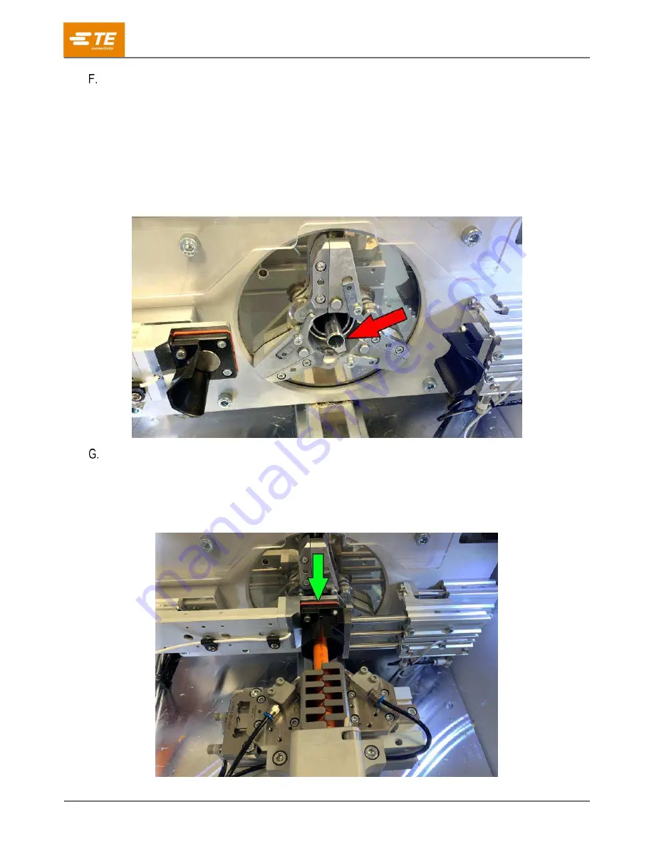
Mandrel
Providing support for the braid to be cut without affecting the inner insulation is the key function of the
mandrel (Figure 18). This component, like the contour blades, is sized specifically for each cable size and
should be paired accordingly (see Table 4 for tooling specifications). During a standard cycle, the mandrel
is inserted under the braid and over the inner insulation. The cutting wheels move into place against the
braid and make a complete cut as the head rotates around the mandrel. The mandrel is a wear item. The
machine warns the user when the mandrel is nearing the end of its life expectancy. This is determined by
the braid cut depth when it reaches its maximum allowable value. The machine does not allow a user to
use a mandrel past this allowable value, preventing the mandrel from breaking during operation.
Figure 18: Mandrel
Cable sensor
When touched by the cable to be processed (Figure 19), the cable sensor initiates machine function. This
feature ensures consistent strip lengths of the cable. It can also be set to automatically run a sequence or
run by operator initiation (button on the user interface).
Figure 19: Cable sensor