background image

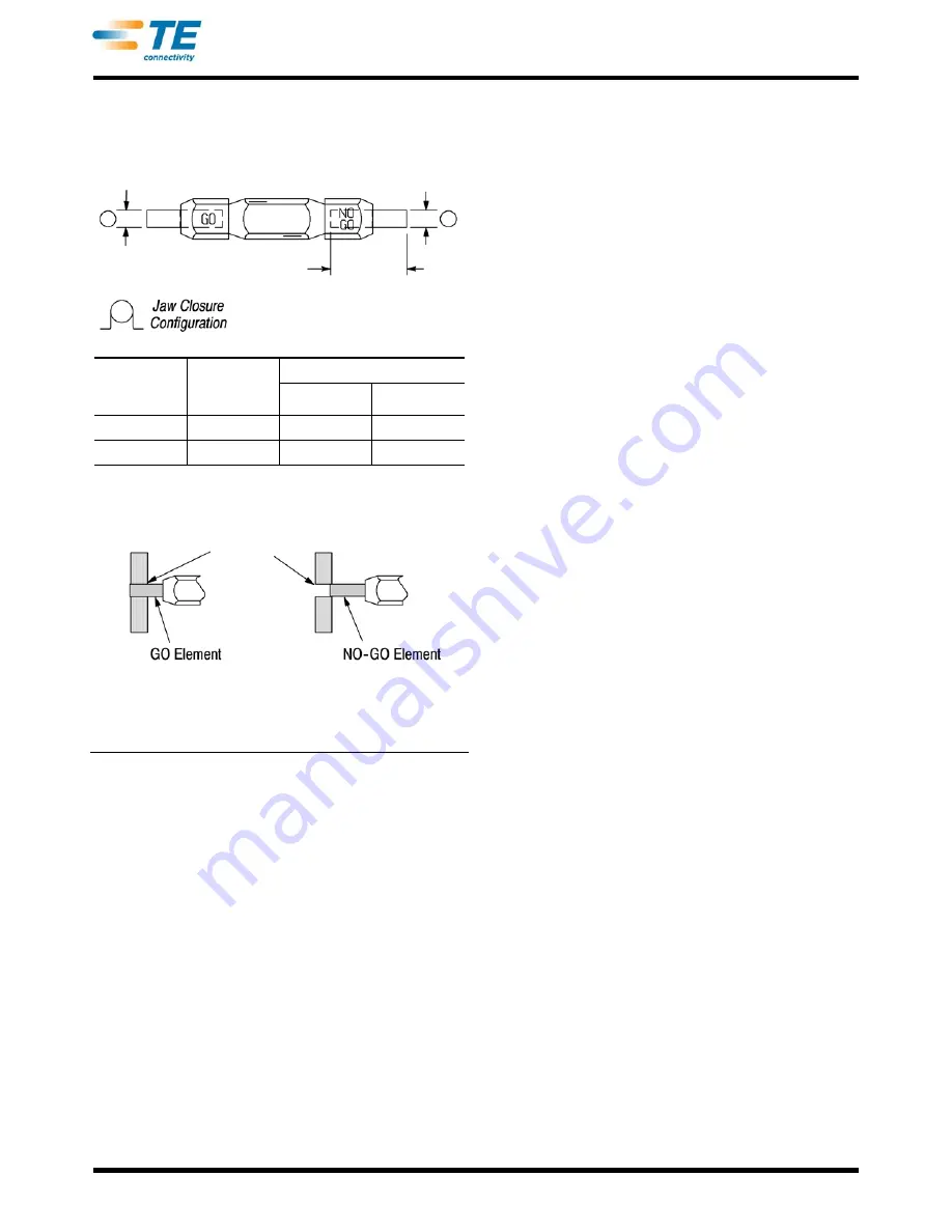
Suggested Plug Gage Design

GO

Diameter

NO-GO

Diameter

19.05 [.750]

Min Typ

TOOL

NO.

CRIMPING 

CHAMBER

MARKING

GAGE ELEMENT DIAMETER

GO

NO-GO

90025

20-16

2.16 [.085]

2.31 [.091]

90026

24-22

1.600 [.063]

1.75 [.069]

Inspection of the Crimping Chamber

Crimping

Chamber 

GO element must 

pass completely 

through the crimping 

chamber.

NO-GO element may enter 

partially, but must not pass 

completely through the 

crimping chamber.

408-1809

4 of 5

Rev B

Figure 4

D. Ratchet Inspection

Obtain a 0.025 [.001] shim that is suitable for checking 
the clearance between the bottoming surfaces of the 
crimping jaws and proceed as follows.

1. Select a terminal and a wire (maximum size) for 
the tool you are using (see Figure 2).

2. Position the terminal and wire between the 
crimping jaws, according to Section 3, CRIMPING 
PROCEDURE (Steps 1 through 5). Holding the wire 
in place, squeeze the tool handles together until the 
CERTI-CRIMP ratchet releases. Hold the tool 
handles in this position, maintaining just enough 
pressure to keep the jaws closed.

3. Check the clearance between the bottoming 
surfaces of the crimping jaws. If the clearance is 
0.025 [.001] or less, the ratchet is satisfactory. If 
clearance exceeds 0.025 [.001], the ratchet is out of 
adjustment and must be repaired (see Section 6, 
REPLACEMENT AND REPAIR).

If the tool conforms to these inspection procedures, 
lubricate it with a THIN coat of any good SAE† 20 
motor oil and return it to service.

6. REPLACEMENT AND REPAIR

Customer-replaceable parts are listed in Figure 5. 
Parts other than those listed in Figure 5 should be 
replaced by TE to ensure quality and reliability of the 
tool. Order replacement parts through your TE 
representative, or call 1-800-526-5142, or send a 
facsimile of your purchase order to 1-717-986-7605, or 
write to:

†  Society of Automotive Engineers

CUSTOMER SERVICE (038-035)

TYCO ELECTRONICS CORPORATION

PO BOX 3608

HARRISBURG PA 17105-3608

For customer repair service, call 1-800-526-5136.

7. REVISION SUMMARY

Revisions to this instruction sheet include:

Changed company name and logo

Summary of Contents for 90025

Page 1: ...for reissue are provided in Section 7 REVISION SUMMARY 2 DESCRIPTION Refer to Figure 1 and Figure 3 The FRONT of the tool has the AMP marking on the link The BACK of the tool wire side into which the wire is inserted has the tool number marked on the handle and the crimp type wire size and type of terminal the tool can crimp PIDG marked on the link Each tool features two crimping jaws a locator tw...

Page 2: ...Make sure ratchet is released squeeze tool handles together and allow them to open FULLY 3 Slide terminal tip through hole in locator until terminal shoulder butts against locator 4 Hold terminal in this position and squeeze tool handles together just enough so crimping jaws hold terminal in place Do NOT deform insulation barrel or wire barrel 5 Insert a properly stripped wire into terminal wire b...

Page 3: ...aces should be protected with a THIN coat of any good SAE 20 motor oil Do not oil excessively SAE is the Society of Automotive Enginners 4 When the tool is not in use keep handles closed to prevent objects from becoming lodged in the crimping jaws Store the tool in a clean dry area 5 2 Periodic Inspection A Lubrication Lubricate all pins pivot points and bearing surfaces with SAE 20 motor oil as f...

Page 4: ...s Hold the tool handles in this position maintaining just enough pressure to keep the jaws closed 3 Check the clearance between the bottoming surfaces of the crimping jaws If the clearance is 0 025 001 or less the ratchet is satisfactory If clearance exceeds 0 025 001 the ratchet is out of adjustment and must be repaired see Section 6 REPLACEMENT AND REPAIR If the tool conforms to these inspection...

Page 5: ...4 2 1 23619 6 1 23619 6 Pin Retaining 187 Dia x 521 L 2 3 21045 6 21045 6 Ring Retaining 2 4 2 23620 9 2 23620 9 Pin Retaining 250 Dia x 838 L 1 5 39364 39364 Spring Handle 1 6 39207 39207 Pin Insulation Adjustment 2 7 125083 1 125083 2 Locator 1 8 3 21016 7 3 21016 7 Screw 1 408 1809 5 of 5 Rev B Figure 5 ...

Reviews: