background image

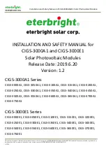
                                              Installation and Safety Manual of CIGS-3000A1&E1 Solar Photovoltaic Module


This document and all information contained herein is the sole property of ETERBRIGHT SOLAR CORPORATION and shall not be distributed, reproduced, or 
disclosed in whole or in part without the prior written consent of ETERBRIGHT SOLAR CORPORATION. 

A3-224


7.


General Installation 


Installation shall be in accordance with CSA C22.1, Safety Standard for Electrical 
Installations, Canadian Electrical Code, Part I. 


This product must be installed by a licensed electrician in accordance with the 
applicable electrical code (i.e. the NEC for the USA and CEC for Canada) 

7.1 Site Selection 


In most applications, the solar photovoltaic module should be installed in a location 
where it will receive maximum sunlight throughout the year. 


For the best results, in the Northern Hemisphere, the module should typically face 
south, and in the Southern Hemisphere, the module should typically face north. The 
appropriate angle of the installation can ensure obtaining the maximum amount of 
sunlight. To understand the best local tilt angle of the information for the installation, 
refer to the ‘Tilt Angle Selection’ or consult a reliable solar systems integrator. 


Do not install the module in a location where it would be easy to produce or gather 
flammable gases. 


The choice of location SHOULD CONFORM to all the requirements of electrical and fire 
regulations. 
 

7.2 Support Selections and Requirements 

To observe the instructions manual and safety practices regarding the attached supports.


Supports and other necessary spare parts, materials (such as bolts, etc.) should be 
made of durable, corrosion-resistant and UV-resistant material.


When installing a module on a pole, choose a pole and module mounting structure that 
will withstand the anticipated winds for the area. 


DO NOT attempt to drill holes in the glass surface of the modules as this will void the 
warranty. 


DO NOT drill additional mounting holes in the module frames of the modules as this 
will void the warranty. 


For standard installation, use the four symmetry mounting holes close to the inner side 
on the module frame to fix the module onto the support. In strong winds or heavy 
snow areas, use additional symmetry holes which are on the outer side of module 
frame for enhancing fixation. For details, please refer to module installation method. 


Summary of Contents for CIGS-3000A1 Series

Page 1: ...N AND SAFETY MANUAL for CIGS 3000A1 and CIGS 3000E1 Solar Photovoltaic Modules Release Date 2019 6 20 Version 1 2 CIGS 3000A1 Series CIGS 3000A1 CIGS 3050A1 CIGS 3100A1 CIGS 3150A1 CIGS 3200A1 CIGS 32...

Page 2: ...stributed reproduced or disclosed in whole or in part without the prior written consent of ETERBRIGHT SOLAR CORPORATION A3 224 Contents 1 Introduction 2 Disclaimer of Liability 3 General Information 4...

Page 3: ...ponsibility is assumed by ETERBRIGHT SOLAR CORPORATION for any infringement of patents or other rights of third parties which may result from the use of the PV product No license is granted by implica...

Page 4: ...bjects on the module Do not drop the module heavily 5 2 Installation Safety DO NOT DISCONNECT UNDER LOAD COMPLETELY cover the module with an opaque material during installation to prevent electricity...

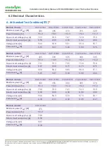
Page 5: ...t PMPP A 5 51 5 57 5 63 5 69 5 75 Module models CIGS 3250A1 CIGS 3300A1 CIGS 3350A1 CIGS 3400A1 CIGS 3450A1 Minimum power PMPP W 325 330 335 340 345 Power tolerance 5 3 5 3 5 3 5 3 5 3 Open circuit vo...

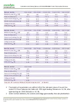
Page 6: ...V 73 1 73 3 73 5 73 6 73 8 Short circuit current ISC A 6 67 6 69 6 71 6 73 6 75 Voltage at PMPP V 55 9 56 2 56 5 56 9 57 1 Current at PMPP A 5 81 5 87 5 93 5 98 6 04 Module models CIGS 3500E1 CIGS 355...

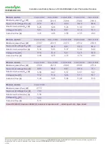
Page 7: ...Module models CIGS 3000A1 CIGS 3050A1 CIGS 3100A1 CIGS 3150A1 CIGS 3200A1 Minimum power PMPP W 220 8 224 6 228 4 232 2 236 0 Open circuit voltage VOC V 67 9 68 1 68 3 68 4 68 6 Short circuit current...

Page 8: ...250E1 CIGS 3300E1 CIGS 3350E1 CIGS 3400E1 CIGS 3450E1 Minimum power PMPP W 239 7 243 5 247 3 251 2 254 9 Open circuit voltage VOC V 68 7 68 9 69 1 69 2 69 4 Short circuit current ISC A 5 34 5 35 5 37...

Page 9: ...ance Level 6 3 Thermal Characteristics NMOT 46 2 2 Temperature Coefficient of Isc 0 01 K Temperature Coefficient of Voc 0 27 K Temperature Coefficient of Pmax 0 28 K 6 4 Mechanical Data Dimension L W...

Page 10: ...IGHT SOLAR CORPORATION A3 224 IP Rating of Junction Box IP67 Adhesive of Junction Box Silicone Gel Connectors MC4 or Compatible Connectors Cables Section 4 0mm2 12AWG Length 1200mm 6 5 Bypass Diode Ty...

Page 11: ...l tilt angle of the information for the installation refer to the Tilt Angle Selection or consult a reliable solar systems integrator Do not install the module in a location where it would be easy to...

Page 12: ...in buildings and structures roofs appearance bearing etc have sufficient loading capacity When installing the module ensure that the module is installed in a fireproof roof and the slope of the roof i...

Page 13: ...th the requirements of UL 1703 unless the module is mounted with hardware that has been tested and evaluated with the module under this standard or by a field Inspection certifying that the installed...

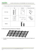
Page 14: ...t be distributed reproduced or disclosed in whole or in part without the prior written consent of ETERBRIGHT SOLAR CORPORATION A3 224 Recommended minimum clamp dimension mm as in following diagrams To...

Page 15: ...ion Under normal conditions a photovoltaic module is likely to produce more current and or voltage than reported under standard test conditions Accordingly the values of Isc and Voc marked on this mod...

Page 16: ...cording to local regulations e g the NEC National Electric Code in the United States If the building is already equipped with an exterior lightning protection system the PV installation must be integr...

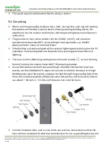
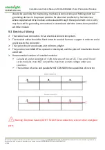
Page 17: ...r grounding connections in accordance with the instructions provided with the module 9 3 Electrical Wiring The cables have connectors for an electrical connection system The module cables should be fi...

Page 18: ...connections every six months or shorter to verify that they are clean secure undamaged and free of corrosion When replacement parts are required the installer or servicer should ensure that parts uses...

Page 19: ...2Revision History Version Details Release Date A Initial Release 2015 09 09 B Add Power Grade 2015 09 25 C 1 Correct 6 3 thermal characteristics and 6 4 front cover 2 Update 6 6 Module Physical Specif...

Reviews: