background image

                                              Installation and Safety Manual of CIGS-3000A1&E1 Solar Photovoltaic Module


This document and all information contained herein is the sole property of ETERBRIGHT SOLAR CORPORATION and shall not be distributed, reproduced, or 
disclosed in whole or in part without the prior written consent of ETERBRIGHT SOLAR CORPORATION. 

A3-224


9.4 Start Generation System 


For a photovoltaic generation system connected to the power grid, you MUST 
CONFIRM that the system has passed the inspection, testing and shall comply with 
regulatory requirements. 


10


  Maintenance 


Clean the glass surface of the module when required. Always use clean water and a 
soft sponge or cloth for cleaning. 


It is recommended to check the electrical, grounding and mechanical connections 
every six months or shorter to verify that they are clean, secure, undamaged and free 
of corrosion. 


When replacement parts are required, the installer or servicer should ensure that parts 
uses are specified by the manufacturer, with the same characteristics as the original 
parts. Unauthorized substitutions may result in fire, electric shock, or other hazard. 


At the suitable moment, maintain the parts used in the system, such as 

brackets, 

charging rectifiers, inverters, batteries, etc.


11


  Shut Down Generation System 


To prevent the generation of electricity during disassembly of the conductor, an 
opaque material must be used to COMPLETELY cover the photovoltaic module. 


In disconnecting the system from the power grid, each component used in the 
system must comply with the operating instructions. 


After the system stops running, it then can be disassembled. 

During operation, 

comply with ALL applicable safety of installation guides.


Summary of Contents for CIGS-3000A1 Series

Page 1: ...N AND SAFETY MANUAL for CIGS 3000A1 and CIGS 3000E1 Solar Photovoltaic Modules Release Date 2019 6 20 Version 1 2 CIGS 3000A1 Series CIGS 3000A1 CIGS 3050A1 CIGS 3100A1 CIGS 3150A1 CIGS 3200A1 CIGS 32...

Page 2: ...stributed reproduced or disclosed in whole or in part without the prior written consent of ETERBRIGHT SOLAR CORPORATION A3 224 Contents 1 Introduction 2 Disclaimer of Liability 3 General Information 4...

Page 3: ...ponsibility is assumed by ETERBRIGHT SOLAR CORPORATION for any infringement of patents or other rights of third parties which may result from the use of the PV product No license is granted by implica...

Page 4: ...bjects on the module Do not drop the module heavily 5 2 Installation Safety DO NOT DISCONNECT UNDER LOAD COMPLETELY cover the module with an opaque material during installation to prevent electricity...

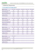
Page 5: ...t PMPP A 5 51 5 57 5 63 5 69 5 75 Module models CIGS 3250A1 CIGS 3300A1 CIGS 3350A1 CIGS 3400A1 CIGS 3450A1 Minimum power PMPP W 325 330 335 340 345 Power tolerance 5 3 5 3 5 3 5 3 5 3 Open circuit vo...

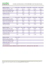
Page 6: ...V 73 1 73 3 73 5 73 6 73 8 Short circuit current ISC A 6 67 6 69 6 71 6 73 6 75 Voltage at PMPP V 55 9 56 2 56 5 56 9 57 1 Current at PMPP A 5 81 5 87 5 93 5 98 6 04 Module models CIGS 3500E1 CIGS 355...

Page 7: ...Module models CIGS 3000A1 CIGS 3050A1 CIGS 3100A1 CIGS 3150A1 CIGS 3200A1 Minimum power PMPP W 220 8 224 6 228 4 232 2 236 0 Open circuit voltage VOC V 67 9 68 1 68 3 68 4 68 6 Short circuit current...

Page 8: ...250E1 CIGS 3300E1 CIGS 3350E1 CIGS 3400E1 CIGS 3450E1 Minimum power PMPP W 239 7 243 5 247 3 251 2 254 9 Open circuit voltage VOC V 68 7 68 9 69 1 69 2 69 4 Short circuit current ISC A 5 34 5 35 5 37...

Page 9: ...ance Level 6 3 Thermal Characteristics NMOT 46 2 2 Temperature Coefficient of Isc 0 01 K Temperature Coefficient of Voc 0 27 K Temperature Coefficient of Pmax 0 28 K 6 4 Mechanical Data Dimension L W...

Page 10: ...IGHT SOLAR CORPORATION A3 224 IP Rating of Junction Box IP67 Adhesive of Junction Box Silicone Gel Connectors MC4 or Compatible Connectors Cables Section 4 0mm2 12AWG Length 1200mm 6 5 Bypass Diode Ty...

Page 11: ...l tilt angle of the information for the installation refer to the Tilt Angle Selection or consult a reliable solar systems integrator Do not install the module in a location where it would be easy to...

Page 12: ...in buildings and structures roofs appearance bearing etc have sufficient loading capacity When installing the module ensure that the module is installed in a fireproof roof and the slope of the roof i...

Page 13: ...th the requirements of UL 1703 unless the module is mounted with hardware that has been tested and evaluated with the module under this standard or by a field Inspection certifying that the installed...

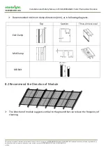
Page 14: ...t be distributed reproduced or disclosed in whole or in part without the prior written consent of ETERBRIGHT SOLAR CORPORATION A3 224 Recommended minimum clamp dimension mm as in following diagrams To...

Page 15: ...ion Under normal conditions a photovoltaic module is likely to produce more current and or voltage than reported under standard test conditions Accordingly the values of Isc and Voc marked on this mod...

Page 16: ...cording to local regulations e g the NEC National Electric Code in the United States If the building is already equipped with an exterior lightning protection system the PV installation must be integr...

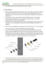
Page 17: ...r grounding connections in accordance with the instructions provided with the module 9 3 Electrical Wiring The cables have connectors for an electrical connection system The module cables should be fi...

Page 18: ...connections every six months or shorter to verify that they are clean secure undamaged and free of corrosion When replacement parts are required the installer or servicer should ensure that parts uses...

Page 19: ...2Revision History Version Details Release Date A Initial Release 2015 09 09 B Add Power Grade 2015 09 25 C 1 Correct 6 3 thermal characteristics and 6 4 front cover 2 Update 6 6 Module Physical Specif...

Reviews: