READ THIS FIRST:
Check the pack and make sure you have all of the
parts listed on the front of this booklet. If not,
contact the outlet where you bought this product.
This product must be installed by a competent
person in accordance with the current building and
IEE wiring regulations.
As the buyer, installer and/or user of this product it
is your own responsibility to ensure that this fitting
is fit for the purpose for which you have intended
it. Eterna Lighting cannot accept any liability for
loss, damage or premature failure resulting from
inappropriate use.
This product is designed and constructed according
to the principles of the appropriate British Standard
and is intended for normal domestic service. Using
this fitting in any other environments may result in
a shortened working life, for example where there
is prolonged periods of use or higher than normal
ambient temperatures such as lighting public or
shared spaces or in nursing /care home facilities.
Switch off the mains before commencing installation
and remove the appropriate circuit fuse or lock off
MCB.
Suitable for outdoor use.
This product is designed for permanent connection
to fixed wiring: this must be a suitable circuit
(protected with the appropriate MCB or fuse).
This product is suitable for installation on surfaces
with normal flammability e.g. wood, plasterboard
and masonry. It is not suitable for use on highly
flammable surfaces (e.g. polystyrene, textiles).
Before making fixing hole(s), check that there are no
obstructions hidden beneath the mounting surface
such as pipes or cables.
The chosen location of your new fitting should
allow for the product to be securely mounted (e.g.
to a ceiling joist) and safely connected to the mains
supply (lighting circuit).
When making connections ensure that the terminals
are tightened securely and that no strands of wire
protrude. Check that the terminals are tightened
onto the bared conductors and not onto any
insulation.
This product must be connected to earth
termination.
This product is not intended to be used by children
and persons with sensory, physical and/or mental
impairments that would prevent them from using it
safely.
You are advised at every stage of your installation to
double-check any electrical connections you have
made. After you have completed your installation
there are electrical tests that should be carried out,
these tests are specified in the current IEE wiring and
building regulations.
INTRODUCTION:
The LED Aluminium Wall Light incorporates a
microwave sensing device which continuously scans
the operating zone and immediately switches the
light on when it detects movement in that area.
This means that whenever movement is detected
within the range of the sensor the light will switch
on automatically and illuminate the area you have
selected to light. While there is movement within
range of the unit the light will remain on.
A microwave sensor is an active motion detector
emitting high-frequency electro-magnetic waves at
5.8GHz and receiving their echo. The sensor detects
change in the echo pattern within its detection
zone and the light is then triggered. The wave can
pass through doors, glass and thin walls and will
continually monitor the signal within the detection
area.
LAMP REPLACEMENT:
INSTALLATION:
Isolate mains and lock off.
Choose the location for your new fitting according to
the conditions listed opposite.
01. Undo the screws retaining the trim and lift off.
02. Loosen gear tray screws and rotate to remove.
03) Using the back of your fitting as a template,
mark the position of your fixing holes on your
mounting surface.
04) Prepare the holes in your mounting surface as
appropriate for your fixings.
05) Pierce the rubber grommet in the back of your
fitting making a hole just large enough to make a
tight fit around the incoming mains cable.
06) Thread the cable through the grommet and offer
the fitting to the ceiling / wall.
07) Secure the fitting in place.
08) Check that the grommet is still correctly fitted in
the cable entry hole and around the incoming
cable.
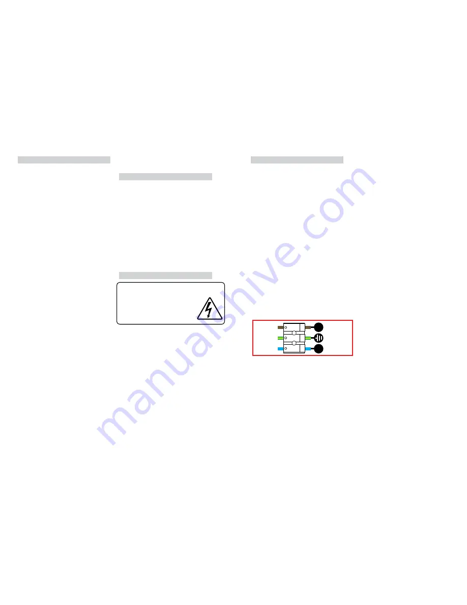
09) Make the electrical connections according to the
symbols, adjacent to the connector block:
Brown to live (L)
Blue to neutral (N)
Earth green & yellow (E)
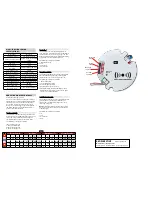
10) Set the multi-function sensor. (See
“understanding the controls” instructions on next
page).
11) Connect the plug / socket between terminal
block & gear tray.
12) Replace gear tray and screw in position with the
three screws.
NOTE:
For eyelid fittings - ensure the arrows on
the gear tray and base match up.
13) Offer the diffuser onto the top of the fitting and
secure in place with the trim.
14) Restore the power and switch on.
The light source contained in this luminaire
shall only be replaced by the manufacturer,
service agent or a similar qualified person.
CAUTION, RISK OF ELECTRIC SHOCK.
The light source is designed to last the lifetime of the
luminaire.
Yellow/Green
EARTH
L
N
Blue/Black
Brown/Red
NEUTRAL
LIVE

