TMCM-1310 TMCL Firmware V1.11 Manual (Rev. 1.16 / 2014-MAR-19)
65
www.trinamic.com
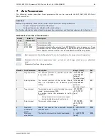
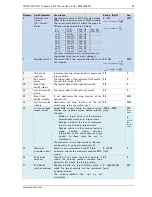
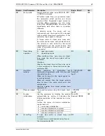
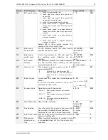
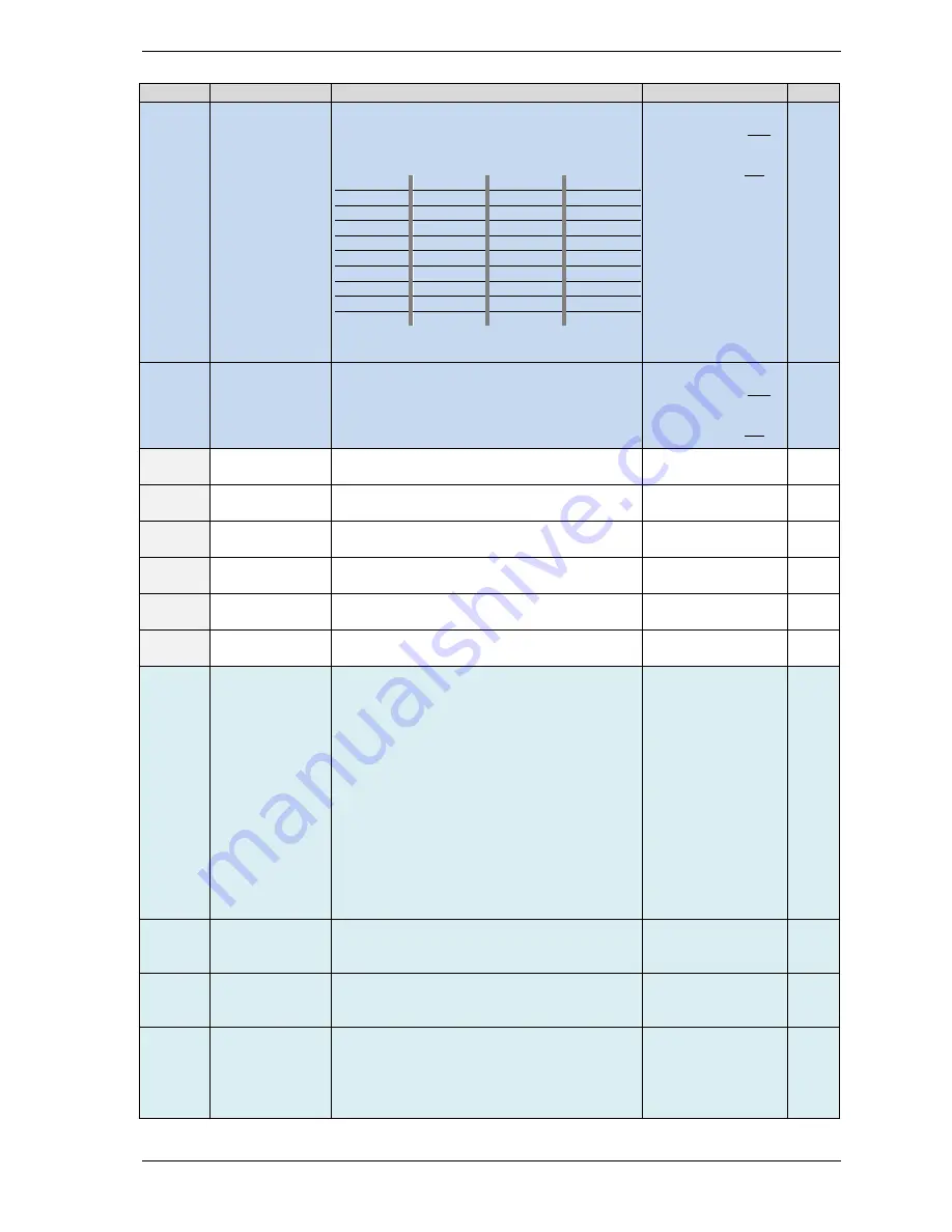
Number Axis Parameter Description
Range [Unit]
Acc.
6
Absolute max.
current
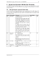
(CS / Current
Scale)
The maximum value is 255. This value means
100% of the maximum current of the module.
The current adjustment is within the range 0…
255 and can be adjusted in 32 steps.
The most important motor setting, since too
high values might cause motor damage!
0… 7
79…87
160… 167
240… 247
8… 15
88… 95
168… 175
248… 255
16… 23
96… 103
176… 183
24… 31
104… 111
184… 191
32… 39
112… 119
192… 199
40… 47
120… 127
200… 207
48… 55
128… 135
208… 215
56… 63
136… 143
216… 223
64… 71
144… 151
224… 231
72… 79
152… 159
232… 239
0… 255
RWE
7
Standby current The current limit two seconds after the motor
has stopped.
00… 255
RWE
8
Target pos.
reached
Indicates that the actual position equals the
target position.
0/1
R
9
Ref. switch
status
The logical state of the reference (left) switch.
Connect this switch to IN1.
0/1
R
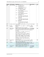
10
Right limit
switch status
The logical state of the right limit switch.
0/1
R
11
Left limit switch
status
The logical state of the left limit switch.
0/1
R
12
Right limit
switch disable
If set, deactivates the stop function of the
right switch
0/1
RWE
13
Left limit switch
disable
Deactivates the stop function of the left
switch resp. reference switch if set.
0/1
RWE
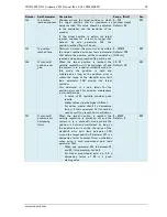
14
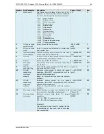
CL torque mode
target current
Target RMS current value for torque mode.
Positive and negative values define rotation
direction.
-
Writing a target value to this parameter
automatically switches to torque mode.
-
Reading provides the actual configured
target current while in torque mode.
-
Reading while in other modes (velocity
mode,
position
mode)
provides
information on the
actual advance angle
(=delta). In these cases the unit is
microsteps).
The maximum current that can be configured
can be read out using axis parameter 15.
-3000… +3000
[mA]
RW
torque
mode
R
velocity
and
position
mode
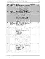
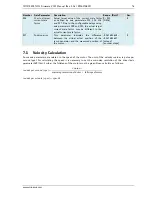
15
Maximum
possible current
Based on axis parameters 6 and 179 this
parameter returns the maximum possible RMS
current.
0….+3000
[mA]
R
16
CL velocity
reached
This flag is set when the actual velocity is
within the velocity reached window (axis
parameter 17) around the target position.
0/1
R
17
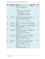
CL Velocity
reached window
Window around the target velocity value in
which the target velocity will be considered
as being reached.
The
velocity_reached
flag will be set
accordingly.
0… +268.435.454
[pps]
RW

