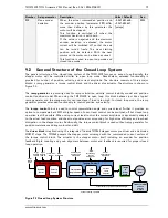
TMCM-1310 TMCL Firmware V1.11 Manual (Rev. 1.16 / 2014-MAR-19)
89
www.trinamic.com
E
XPLANATIONS RELATED TO
F
IGURE
9.6
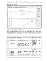
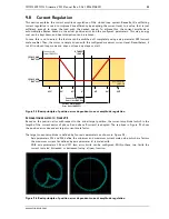
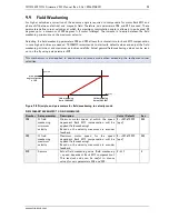
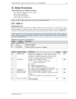
Figure 9.6 shows the two phase currents for phase A and B as XY-diagram on a scope using two current
probes. They show the difference between
current regulator enabled
(left) and
disabled
(right). One
complete circle represents a full electrical period of 360°. On the left side, current level regulation is
switched on. When moving the rotor away from its target position (in this example somewhere in the
lower right quadrant) the current amplitude is increased based on the position error up to its configured
maximum amplitude. When approaching the target position the current level is decreased again. On the
right side, the current regulation is switched off and current amplitude is always on the configured
maximum regardless if there is a position error or not.
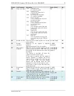
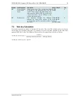
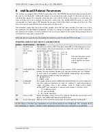
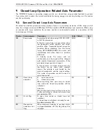
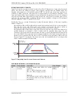
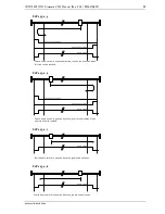
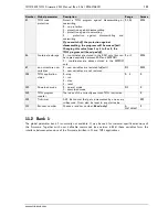
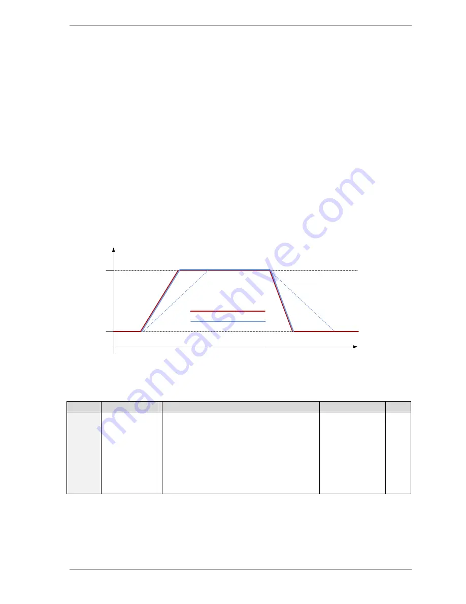
Additionally, there are a couple of parameters to adapt the dynamic behavior of the current regulation
(shown in Figure 9.7):
-
Axis parameters 118 and 119 configure the increment and decrement value for the current scale factor.
Each time the current scale factor needs to be increased or decreased this value is added or
subtracted from the actual value until the actual target current scale factor is reached.
-
Axis parameters 120 and 121 define a delay timer value. Each time the current scale factor needs to be
updated (increased or decreased) a timer is started with the respective delay value. The next
increment or decrement will only be done when the timer is zero. If the parameters 120 and 121 are
set to zero (default), the current scale factor is always directly set to the target current scale factor as
defined by axis parameters 113, 114, 116, and 117. The effects of axis parameters 120 and 121 are
shown in Figure 9.7. For example, the current scale value can immediately be set to its target value
while it will be decreased with some delay.
Time
0
Actual Current Scale Target Value
Actual Current Scale Value
SA
P
12
0
=
0
SA
P
12
0
> 0
SA
P 1
21
> 0
SA
P
12
1
= 0
I_SCALE_MAX
(SAP 114)
I_SCALE_MIN
(SAP 113)
Current Scale
Factor (GAP 123)
Figure 9.7 Using delay times for current increase and decrease
A
XIS PARAMETERS RELATED TO THE CURRENT REGULATION
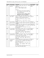
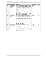
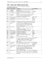
Number Axis parameter
Description
Units / Default
Acc.
113
CL current scale
minimum
Minimum current scale factor for current
regulation.
255 = 1 = 100% of maximum current
127 = 0.5 = 50% of maximum current
…
Attention!
The maximum current itself is defined by the
CS parameter of the motor driver chip (see axis
parameter 6)
Default = 15
[1/256]
RW

