3
B E D I E N U N G
Restricting the temperature range
The temperature setting range of the thermostats can be restricted using the dial.
Example: Setting temperature range to 2-5
-
Adjust the dial to set the device to the average range, in this example therefore 3.
-
Remove the dial carefully using the screwdriver.
-
Use pliers to carefully pull out the retaining pin (located at the bottom in the middle).
-
To turn the blue cog wheel to the lower setting limit 2.
-
Then turn the red cog wheel to the upper setting limit 5.
-
Refit the retaining pin.
-
Refit the setting dial carefully.
You can now only move the dial between settings 2 and 4.
NOTE
The mains supply does not have to be switched off to set the temperature range.
Operation
Switching OFF the heater
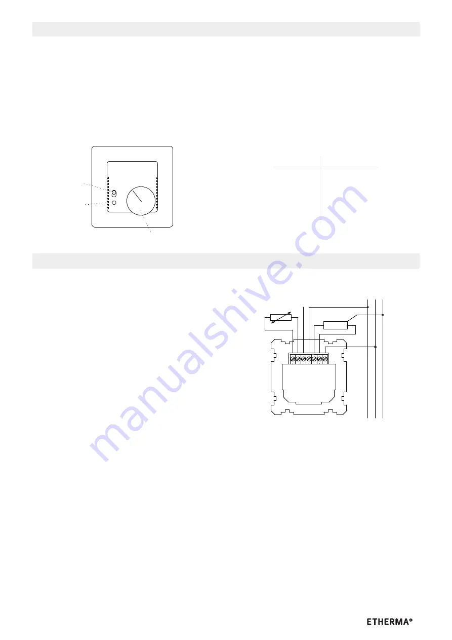
To switch off the heater, move the slide switch (see Fig. 3, pos. 1) down (circle symbol) to OFF
Switching ON the heater
To switch on the heater, move the slide switch up to the ON position (circle/point symbol)
In this mode, the LED will light up when heat is required
Troubleshooting
Symptom
Possible cause/Solution
Heater not functioning
- Switch on / check mains supply
- Check heater
- Check sensor cable
- Check set temperature
Mains supply failure
The heater will switch off in the event of a mains supply failure, break or short-circuit in the sensor cable.
Sensor characteristic:
~~
o
o
~
1
5
3
4
2
Schalter
Heizung
ein / aus
LED für
Heizung ein
Temperatureinstellung
Geräteübersicht
T E C H N I S C H E D A T E N
Electronic Floor Thermostat without Timer
HRT 6007
Important notes
ATTENTION
Work on the 230 V mains supply must only be carried out by authorised electricians.
The safety regulations of the VDE and the local utility company must be observed when connecting the device. The connection
work must not be carried out when the mains supply is switched on. The mains supply cable must be protected by means of a
12 A miniature circuit-breaker.
In rooms with moisture (e.g. bath rooms) a 30 mA residualcurrent circuitbreaker must be installed in accordance with VDE 0100
In the event of a fault the mains voltage may be present on the sensor line.
Application / function
Application
The electronic floor thermostats without timer are designed as individual room temperature controllers. Both electrical and hot
water heaters can be connected to it. In the latter case, 230 V “normally closed” control valves must be used.
Function
The device consists of:
- the control module for setting the required floor temperature using a dial and
- the supplied sensor (floor temperature sensor) which measures the floor temperature and transfers
the measured value to the control module.
.
The ON/OFF slide switch can be used to make a single-pole disconnection of the heating system from the mains supply and thus
switch off the heating.
Technical data
Mains voltage:
230 V ~
10%, 50 Hz
Max. switched current:
approx. 12 (4) A
Max. switching capacity:
2.7 kW
Switching temperature differential:
Approx. 0.7 K
Relay contact:
opens with overtemperature
Required control valve
for hot water heaters:
230 V, normally closed
Temperature sensor:
NTC with 2 k
at 25°C to DIN 44574,
length approx. 4 m ,
approx. 8 mm
Setting range:
Position 1-5, corresponds to 10 to 45°C
Ambient temperature:
-10 to + 40°C
Connection cables:
The cross-section of the connection cables
must be 2.5 mm² for a heat output 2.5 kW
and higher
Energy class:
I = 1.0%
Installation
Position the sensor in a separate protective tube at heating mat level or over the heating mat.
The thermostats are installed using standard flush mounting boxes (to DIN 49073, Part 1). When using additional intermediate
terminals, we recommend the use of a deep switch box (
55 mm).
-
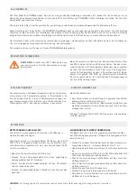
Connections should be carried out in compliance with Fig. 1
-
Fit the slide switch element supplied with the cover onto the corresponding slide switch of the device.
-
Then position the central dial onto the flush mounting unit and screw it tight.
-
Finally fit the adjusting dial with the groove onto the device.
L N PE
(L)
heating
F TAL L1 NN
NTC
Fig.1
F
Netzspannung:
230 V ~ ± 10 %, 50 Hz
Max. Schaltstrom:
ca. 16 A
Max. Schaltleistung:
2,7 kW
Schalttemperaturdifferenz: ca. 0,7 K
Relaiskontakt:
öffnet bei Übertemperatur
Erforderliches Stellventil
bei Warmwasserheizungen: 230 V, stromlos geschlossen
Temperaturfühler:
NTC mit 2 kW bei 25 °C nach
DIN 44574, Länge ca. 4 m, Æ ca. 8 mm
Einstellbereich:
Stellung 1-6, entsprechend
10 bis 60 °C
Umgebungstemperatur:
- 10 bis + 40 °C
Anschlussleitungen:
ab 2,5 kW Heizleistung muss der
Querschnitt der Anschlussleitun-
gen 2,5 mm² betragen
HEIZUNG AUS-SCHALTEN
Zum Ausschalten der Heizung schieben Sie den Schiebeschal-
ter nach unten (Kreis-Symbol) auf AUS.
HEIZUNG EIN-SCHALTEN
Zum Einschalten der Heizung schieben Sie den Schiebeschal-
ter nach oben (Kreis/Punkt-Symbol) auf EIN.
In dieser Betriebsart leuchtet die LED-Anzeige, wenn Wärme
angefordert wird.
STÖRUNGSBESEITIGUNG
DIAGNOSE MÖGL.
URSACHE / ABHILFE
Heizung arbeitet nicht
> Netzspannung anlegen / prüfen
> Heizung prüfen
> Fühlerleitung prüfen
> eingestellte Temperatur prüfen
NETZAUSFALL
Im Falle eines Netzausfalles, Unterbrechung oder Kurz-
schluss der Fühlerleitung, wird die Heizung ausgeschaltet.
FÜHLERKENNLINIE:
Temp °C
Widerstand k
Ω
10
3,66
20
2,43
30
1,66
40
1,15
50
0,82
Netzspannung:
230 V ~ ± 10 %, 50 Hz
Max. Schaltstrom:
ca. 12 A
Max. Schaltleistung:
2,7 kW
Schalttemperaturdifferenz: ca. 0,7 K
Relaiskontakt:
öffnet bei Übertemperatur
Erforderliches Stellventil
bei Warmwasserheizungen: 230 V, stromlos geschlossen
Temperaturfühler:
NTC mit 2 kW bei 25°C nach
DIN 44574, Länge ca. 4 m, Æ ca. 8 mm
Einstellbereich:
Stellung 1-5, entsprechend
10 bis 45 °C
Umgebungstemperatur:
- 10 bis + 40 °C
Anschlussleitungen:
ab 2,5 kW Heizleistung muss der
Querschnitt der Anschlussleitun-
gen 2,5 mm² betragen
TEMPERATURBEREICH BIS 60 °C:
TEMPERATURBEREICH BIS 45 °C:


