4
The safety regulations of the VDE and the local utility company
must be observed when connecting the device. The connection
work must not be carried out when the mains supply is swit-
ched on. The mains supply cable must be protected by means
of a 12 A miniature circuit-breaker. In rooms with moisture (e.g.
bath rooms) a 30 mA residualcurrent circuitbreaker must be
installed in accordance with VDE 0100. In the event of a fault the
mains voltage may be present on the sensor line.
I N S T A L L A T I O N
NOTE:
The mains supply does not have to be switched off to set the temperature range.
A T T E N T I O N : Work on the 230 V mains supply
must only be carried out by authorised electricians.
I M P O R T A N T I N S T R U C T I O N S
G E N E R A L
A P P L I C A T I O N
F U N C T I O N A L I T Y
The electronic floor thermostats without timer are designed as
individual room temperature controllers. Both electrical and
hot water heaters can be connected to it. In the latter case, 230 V
“normally closed” control valves must be used.
The device consists of:
> the control module for setting the required floor temperature
using a dial and
> the supplied sensor (floor temperature sensor) which mea-
sures the floor temperature and transfers the measured va-
lue to the control module.
The ON/OFF slide switch can be used to make a single-pole
disconnection of the heating system from the mains supply and
thus switch off the heating.
SWITCH OFF MAINS VOLTAGE!
Lay remote sensor in a separate protective tube in the floor in
the heating mat level.
The thermostats are installed using standard flush mounting
boxes (to DIN 49073, Part 1). When using additional interme-
diate terminals, we recommend the use of a deep switch box
(Æ 55 mm).
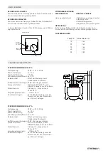
> Connections should be carried out in compliance with Fig. 1
> Fit the slide switch element supplied with the cover onto the
corresponding slide switch of the device.
> Then position the central dial onto the flush mounting unit
and screw it tight.
> Finally fit the adjusting dial with the groove onto the device.
RESTRICTING THE TEMPERATURE RANGE
The temperature setting range of the thermostats can be
restricted using the dial. Example: Setting temperature range
to 2-5
> Adjust the dial to set the device to the average range, in this
example therefore 3.
> Remove the dial carefully using the screwdriver.
> Use pliers to carefully pull out the retaining pin (located at the
bottom in the middle).
> To turn the blue cog wheel to the lower setting limit 2.
> Then turn the red cog wheel to the upper setting limit 5.
> Refit the retaining pin.
> Refit the setting dial carefully.
> You can now only move the dial between settings 2 and 4.
With your choice for ETHERMA you have decided on an ingenious heat solution. Thank you for your trust. In us you have a compe-
tent partner with more than 30 years of experience. ETHERMA relies on constant innovation, highest product quality and modern
design.
We support you with extensive services and find the individually suitable product solution for you.
This manual should help you to use your ETHERMA quality product as effectively as possible. It provides important information
for the safety, installation, use and maintenance of the equipment. Please read the information in this manual carefully and keep
it for further reference at a later date.
The manufacturer will not be liable if the following instructions are not followed. The devices must not be abusive, i. contrary to
the intended use.
We hope you enjoy your ETHERMA quality product.


