23
EN
23
EN
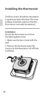
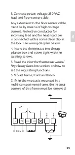
3. Connect power, voltage 230 VAC,
load and floor sensor cable.
Any extension to the floor sensor cable
must be by means of high-voltage
current. Protective conductor for
incoming feed and for heating cable
is connected with a connection clip in
the box. See wiring diagram below.
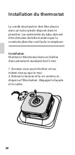
4. Insert the thermostat into the ap-
pliance box and screw tight with the
existing screws.
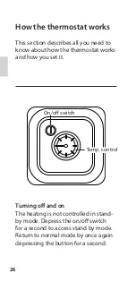
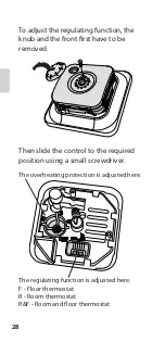
5. Read the
How the thermostat works/
Regulating functions
section on how to
set the regulating functions.
6. Mount frame, front and knob.
7. If the thermostat is mounted in a
multi-compartment frame, the internal
corners of this frame must be removed.
LOAD
LOAD
N
L
SENSOR
SENSOR
DO NO
T USE
230 V
Summary of Contents for ET-71
Page 1: ...HANDBUCH MANUAL MANUEL HANDMATIG DE EN FR NL ET 71...
Page 2: ......
Page 3: ...1 DE Deutsch English Fran ais 2 18 34 EN NL FR 1 DE Nederlands 50 EN NL FR...
Page 4: ...2 2...
Page 20: ...18 18...
Page 36: ...34 34...
Page 52: ...50 50...

