background image

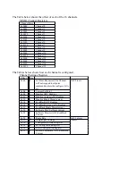
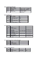
 Latched Input Status (0x0010)

Bit
[31:09]
8

Water Fault  (Turn off Bulk)

[07:00]

Inputs

Clear Latched Input Status (0x0014)

Bit
[31:09]
8

Water Fault  (Turn off Bulk)

[07:00]

Inputs

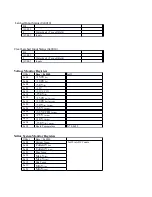
Voltage Monitor Registers

Offset

Base = 0x0540

Int32

0x00

+15.0V

(In)

0x04

+12.0V

(In)

0x08

+5.0V

(In)

0x0C

+3.3V

0x10

+3.3VCC IO

0x14

-15.0V

(In)

0x18

+15.0V

(In) Current

0x1C

+12.0V

(In) Current

0x20

+5.0V

(In) Current

0x24

+3.3V

 Current

0x28

+3.3VCCIO

 Current

0x2C

+2.5V

 Current

0x30

+1.0V

 Current

0x34

-15.0V

(In) Current

0x38

Board Temperature

N* 0.0625

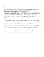
Xilinx System Monitor Registers

Offset

Base = 0x0580

0x00

Current Temp

Int32 in ADC Counts

0x04

Current V

(Int)

0x08

Current V

(Aux)

0x0C

Max Temp

0x10

Max V

(Int)

0x14

Max V

(Aux)

0x18

Min Temp

0x1C

Min V

(Int)

0x20

Min V

(Aux)

Summary of Contents for EMCOR

Page 1: ...User s Manual Ethernet MCOR EMCOR Controller Module ...

Page 2: ...EMCOR module J1 and J2 signal connections 5 6 Table of Crate J3 and J4 connections to EMCOR J1 connections 6 7 Description of EXT INTLK Connection 7 8 Description of Crate OK Connection 7 9 EMCOR Crate USB Diagnostic Application 7 10 EMCOR Front Panel Description 17 11 Remote PCI Register Information 18 12 Base Address Register Table 19 13 MCOR Faults Registers Table 23 14 EMCOR Module CPU Boot Up...

Page 3: ...used to control MCOR modules unless the USB Diagnostic Application is being used Instructions for the CPU boot up process which loads the OS into the CPU module can be found later in this document Note that due to the amount of heat generated by the CPU module it is necessary to always make certain that a blower assembly is installed to the crate and that air flow is constantly available across th...

Page 4: ...ly location in the crate with the 2 connectors P1 and P2 necessary to mate with the EMCOR module The EMCOR module will receive the required power needed from the crate power supply via crate connection P1 and EMCOR module connection J2 The EMCOR module will control up to 16 MCOR modules using a GUI based software such as EPICS and the EMCOR front panel EPICS CA port Figure 1 Jumper locations W7 P2...

Page 5: ...6 FDBK_0 B6 FDBK_4 C6 FDBK_8 A7 15V_IN_AUX B7 MAG_FAULT3 C7 INTLK4 A7 GND_1 B7 GND_5 C7 GND_9 A8 15V_IN_AUX B8 MAG_FAULT4 C8 INTLK4 A8 REF_1 B8 REF_5 C8 REF_9 A9 15V_IN_AUX B9 5V_D C9 MAG_FAULT5 A9 AGND B9 AGND C9 AGND A10 5V_IN_AUX B10 AD7_CS C10 MAG_FAULT6 A10 MON_1 B10 MON_5 C10 MON_9 A11 5V_IN_AUX B11 AD7_DOUTA C11 MAG_FAULT7 A11 MCOR_FAULT1 B11 MCOR_FAULT5 C11 MCOR_FAULT9 A12 5V_IN_AUX B12 AD...

Page 6: ...ignal Name Corresponding Crate J4 Pin A1 15V_IN_AUX A1 A13 AD6 RESET A1 A2 15V_IN_AUX A2 A14 AD6 FDATA A2 A3 5V_IN_AUX A3 A15 AD6 CONVST A3 A4 5V_IN_AUX A4 A16 AD6 SCLK A4 A5 DGND A5 A17 AD6 CS A5 A6 DGND A6 A18 AD6 DOUTA A6 A7 15V_IN_AUX A7 A19 AD6 DOUTB A7 A8 15V_IN_AUX A8 A20 AD6 BUSY A8 A9 15V_IN_AUX A9 A21 AD6 REFSEL A9 A10 5V_IN_AUX A10 A22 AD7 RESET A10 A11 5V_IN_AUX A11 A23 AD7 FDATA A11 A...

Page 7: ... the output of the supply with a short across the applicable pins Consult the operator s manual of the power supply in use for more specific information Event Receiver EVR Currently these functions have not yet been implemented Fast Feedback Currently the Fast Feedback function has not yet been developed EMCOR Crate Diagnostic Application This is a Windows based GUI application primarily used as a...

Page 8: ...set selection An Immediate fault can be cleared by using the EMCOR front panel Reset button The Faults display should now appear as shown in screen shot 3 with all MCOR faults appearing in green as shown on the panel and no flashing red LEDs as shown on the MCOR module s It should be noted at this time that even though the Faults panel displays Magnet and External Interlock faults they are not act...

Page 9: ...Screen shot 2 Faults Panel with fault ...

Page 10: ...Screen Shot 3 Faults Panel with no faults Screen Shot 4 Channel Pulldown ...

Page 11: ...eturn key note that there must be a load connected to the output on the back of the crate before any current will flow The Set Point window cannot be set to a value unless the Configured box has been checked Click on the Refresh button for the changes to take effect on the panel display Select the ADC panel from the main panel This panel screen shot 5 will enable the user to monitor any settings m...

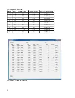
Page 12: ... DAC Full Scale Setting 30 30A 30A 30A 30 7692A 20 20A 20A 20A 20 5128A 12 12A 12A 12A 12 30768A 9 9A 9A 9A 9 23076A 7 5 7 5A 7 5A 7 5A 7 6923A 6 6A 6A 6A 6 15384A 2 2A 2A 2A 2 05128A 1 5 1 5 1 5A 1 5A 1 53846A 1 1 1A 1A 1 02564A Screen Shot 6 ADC Raw Panel 12 ...

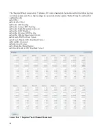
Page 13: ...nt Current Set Point Monitor ADC Reading Monitor Average ADC Reading Monitor Ripple Measurement in uA Feedback ADC Reading Feedback Average ADC Reading Feedback Ripple Measurement in uA Full scale DAC Set Point Current Full scale Monitor ADC Read Back Current Ramp Rate amps sec Samples per Average Configuration Status Register Full scale Feedback ADC Read back Current Screen Shot 7 Registers Panel...

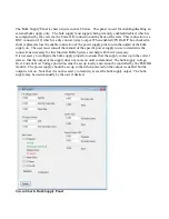
Page 14: ...he manual of the specific power supply in use to determine the connections necessary for this function BiRa Systems can help with this if necessary It is necessary to configure the bulk supply properly to ensure that the supply comes up in the correct state so that the output of the supply does not come on until commanded The bulk supply voltage Over Current Over Voltage protection must be set up ...

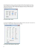
Page 15: ...ear The current values of the 1 0V and 2 5V supply voltages and the temperature of the part will be shown upon clicking the Refresh button Screen Shot 9 Xilinx Monitor To monitor the EMCOR board voltages select the V MON tab from the main panel Screen shot 10 is representative of this panel after clicking the Refresh button Screen Shot 10 EMCOR Board Voltages Panel 15 ...

Page 16: ...16 For System information the Sys Info tab can be used as shown in screen shot 11 Screen Shot 11 Sys Info Panel ...

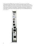
Page 17: ...hat can be seen in the P9 connector is for stability of the boot up process and should not be removed The EVR connector is not active at this time The EPICS CA J5 connector is for Ethernet communication The COM J7 connection port is used for serial communication CPU RST S2 is a switch that when activated will reset the CPU which will cause a re boot of the module to occur The Fast Feedback functio...

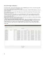
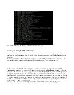
Page 18: ...ng instructions should be used The following instructions assume that the CPU boot up process has completed normally see boot up instructions below Open up a terminal on the LINUX based machine used for the boot up process and enter the following being careful to make the entries exactly as shown cd emcor python package Python RemotePCI GUI Once this information is entered you are in the correct d...

Page 19: ...the address 0x000001c0 into the GUI and request a read of the information in this register In this case the data in the register reads 0x000f4240 The channel settings register tells us this data is a signed integer format with units of uA When translated to decimal the result is 1000000 or the equivalent of 1amp which is the current set point for channel 7 The BAR 0 Base Address Register Memory Ma...

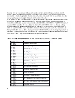
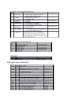
Page 20: ...s Offset Reg 0x00 0 Set Point Requested The Channel will not respond to setpoint commands unless the configure bit is set Int32 in uA 0x04 1 Current Set Point 0x08 2 Monitor ADC Reading 0x0C 3 Monitor Average ADC Reading 0x10 4 Monitor Ripple Measurement 0x14 5 FeedBack ADC Reading 0x18 6 FeedBack Average ADC Reading 0x1C 7 FeedBack Ripple Measurement 0x20 8 Fullscale DAC SetPoint Current 0x24 9 F...

Page 21: ...annel will not respond to setpoint commands unless the configure bit is set Configuration Set Reset Registers Bit 4 Standardized Direction Not implemented 3 Ramp Immediate 2 Closed Loop Not implemented 1 Fast FeedBack Not implemented 0 Configured Ramp Rate Bit 31 00 Ramp Rate Int32 in µA sec Bulk Supply Register Information Offset Reg Base 0x0400 0x04 1 Bulk Supply Voltage 0 5V 0 30V Int32 in µV 0...

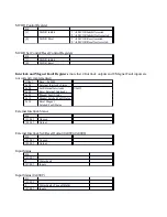
Page 22: ...lk Supply OFF MCOR ADC Control Registers Information Offset Base 0x0440 0x00 Control Uint32 0x04 Set Control 0x08 Reset Control 0x0C MCOR ADC Oversampling 0x10 MCOR ADC External Ref Control Register Bit 3 Bulk ADC Timeout 1 Bulk ADC timed out 0 Bulk ADC OK 2 ADC Timeout 1 One of the ADC s timed out 0 ADC s OK 1 Bulk ADC Reset 1 Bulk ADC Reset Asserted 0 Bulk ADC Reset Not Asserted 0 MCOR ADC s Res...

Page 23: ...edback ADC Channels 7 0 01 Monitor ADC Channels 15 8 00 Monitor ADC Channels 7 0 MCOR Faults Registers Offset Base 0x0480 0x00 MCOR Power Module Fault Status Uint32 0x04 MCOR Power Module Latched Fault Status 0x08 Reset Latched Fault Status 0x0C Control 0x10 Set Control 0x14 Reset Control 0x18 Fault ByPass 0x1C Set Fault Bypass 0x20 Reset Fault Bypass MCOR Fault Status Bit 15 00 MCOR Power Module ...

Page 24: ...lt inputs are not currently implemented Offset Base 0x0500 0x00 External Interlocks Status 0x04 Set External Interlocks UInt32 0x08 Reset External Interlocks 0x0C Magnet Fault Status 0x10 Magnet Latched Fault Status 0x14 Reset Magnet Latched Fault Status External Interlock Status Bit 31 04 Unused 03 00 Output External Interlock Set Reset Output 0x0004 0x0008 Bit 31 04 Unused 03 00 Output Input Sta...

Page 25: ...V In 0x0C 3 3V 0x10 3 3VCC IO 0x14 15 0V In 0x18 15 0V In Current 0x1C 12 0V In Current 0x20 5 0V In Current 0x24 3 3V Current 0x28 3 3VCCIO Current 0x2C 2 5V Current 0x30 1 0V Current 0x34 15 0V In Current 0x38 Board Temperature N 0 0625 Xilinx System Monitor Registers Offset Base 0x0580 0x00 Current Temp Int32 in ADC Counts 0x04 Current V Int 0x08 Current V Aux 0x0C Max Temp 0x10 Max V Int 0x14 ...

Page 26: ...tware Interrupt WO Interrupt Source Bit 31 09 Unused 08 Software Interrupt 07 06 Ramp Done Not Implemented 05 COMx GPI From COMx GPIO 04 BSA Message Available Not Implemented 03 EVR Interrupt 02 OR of the Magnet Faults External Interlocks Not Implemented 01 OR of the MCOR Channel Faults Not Implemented 00 Waveform Acquisition complete Not Implemented Interrupt Source Enables Set Reset Registers Bi...

Page 27: ...l connection and an Ethernet connection The serial connection from the PC to the EMCOR module may use a USB output and serial adapter if a serial port is not available on the PC The connector on the EMCOR module J7 is an Ethernet connection which will require an adapter from the serial connection of the PC The Ethernet connection from the PC will connect directly to the J5 connector on the EMCOR m...

Page 28: ...irectory Type the command cd var lib dhcp which will place you in the directory where the file dhcpd leases resides To edit this file and set the correct MAC address type the command sudo gedit dhcpd leases enter the password when prompted and then enter the correct 12 character MAC address into the file that was recorded during the CPU installation described above the MAC address should also be o...

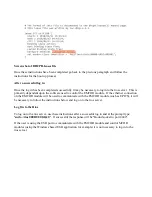
Page 29: ...connection on the EMCOR module will be used to communicate with the EMCOR module such as EPICS it will be necessary to follow the instructions below and log on to the rios server Log On to the Rios To log on to the rios server use these instructions after a successful log in and at the prompt type sudo rios 0000 01 00 0 0 If successful the response will be Bound socket to port 4444 If the user is ...

Reviews: