C4
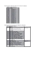
INTLK2-
C4
C16
N/C
C4
C5
C5
C17
DA5 SD0
C5
C6
INTLK3-
C6
C18
DA5 RESET
C6
C7
C7
C19
DA5 LDAC
C7
C8
INTLK4-
C8
C20
DA5 CLR
C8
C9
MAGFAULT5
C9
C21
DA5 SDIN
C9
C10
MAGFAULT6
C10
C22
DA5 SCLK
C10
C11
MAGFAULT7
C11
C23
DA5 SYNC
C11
C12
DGND
C12
C24
N/C
C12
EXT INTLK connection J1
Description
Crate connection J1, which is a BNC connector on the back of the crate labeled "
EXT INTLK",
must
be configured correctly for normal operation of the crate. As is currently the case with the Interface
Controller module, a closed switch must be present across J1 or an MCOR fault will be generated.
The signal name for this connection is 'Water_Sum_Fault'. An open switch will cause +5V on the
water_sum_fault circuits which will generate a fault condition and disable all MCOR modules.
Crate OK connection J2 Description
When properly configured this BNC connection may be used as a dry contact output to enable/disable a
properly configured Bulk Power Supply output.
A properly equipped power supply used as the bulk supply must have a connection available that will
enable the output of the supply with a short across the applicable pins. Consult the operator's manual
of the power supply in use for more specific information.
Event Receiver (EVR)
Currently these functions have not yet been implemented.
Fast Feedback
Currently the Fast Feedback function has not yet been developed.
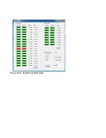
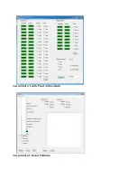
EMCOR Crate Diagnostic Application
This is a Windows based GUI application primarily used as a diagnostic application to monitor and
reset certain faults, set and monitor MCOR channels, and turn on/off a properly configured bulk power
supply. A USB male Type A connection attached to a PC with a USB male Type B connection attached
to EMCOR connector J9 is required for use with this application.
The application may be used as soon as the crate has been powered up and can be used whether the
CPU boot process has been completed or not. If the CPU boot up process is not going to be performed,
both the serial and Ethernet cables (J7 and J5) do not need to be connected. Once the crate is powered
up and the power-up sequence of the EMCOR module has completed, a green (OK) LED on the
EMCOR module should be slowly flashing. A red LED on the MCOR module(s) may also be flashing
(assumes that the bulk supply is connected and enabled, and a closed switch across the crate J1

