EasyPoE Box Series Installation Guide
Copyright 2021 EtherWAN Systems, Inc.
Page 2
All Rights Reserved
EasyPoE Box Series
5/1/2021
4
Configuration
After the unit powers up, connect a PC to the
configuration port (labeled CONF).
IP address will be assigned via DHCP by
default. Make sure that a DHCP server, such
as a router, is available.
Retrieve the IP address from the DHCP server
and access the web configuration page via a
browser using the default credentials below.
Username:
admin
; Password:
private
The EasyPoE Box is a collaboration between
EtherWAN Systems and Phoenix Contact. As
such, you may see references to Phoenix
Contact, this is normal.
For security purposes, make sure to change
the password during initial configuration.
To access the configuration page via a static
IP address, see the section below.
5
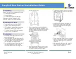
Setting Static IP Address
The operating mode of the switch can be
changed via the Mode button.
If a DHCP server is not available, use the
following method to set up a static IP
address.
After the switch boots up, as soon as all LEDs
turn off, press and hold the Mode button for
at least 5 seconds.
Note that there is a limited amount of time
that the LEDs remain off and if LEDs come on
again, it will not be possible to change the
mode.
Once all LEDs are solid green, release the
button.
The “Exit without change” function is active
by default.
To select the static IP address function, press
the button to toggle between the functions
until the function is chosen.
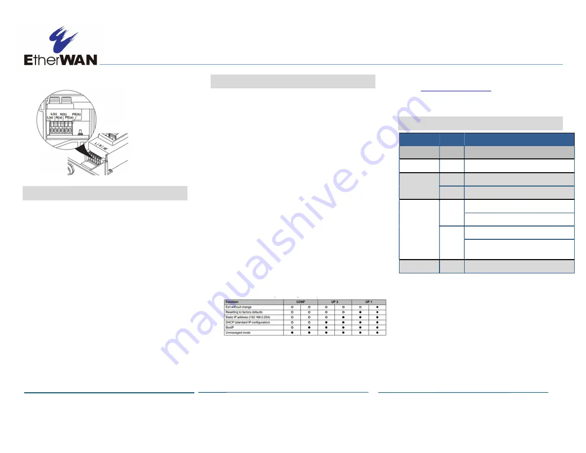
Below is a table of the different functions
with the corresponding LED patterns.
To apply and save the setting, press and hold
the Mode button again for at least 5 seconds
until all LEDs are solid and release the
button.
In a web browser, type the static IP address
of
http://192.168.0.254
in the address bar
and log in to the switch.
6
System LEDs
LED
Color
Status
PWR
Green
On = Device switched on
AUX
Green
On = 24VDC output
LINK
Green
ON = 10/100M
Orange ON = 1000M
PoE
Green
FLASH = Searching for powered device (PD)
ON = Power supplied to PD
Orange ON = Force mode, PoE voltage present
FLASH = Error, e.g. negotiated performance
exceeded
All LEDs
Green
ON = Boot process.


