EX62000 Managed Switch Installation Guide
Copyright
©
2014 EtherWAN Systems, Inc.
Page 2
All Rights Reserved
EX62000 rev. 1.0
12/2/2014
Power-Up Sequence
When you apply power, all
Link/ACT
LEDs blink
momentarily, the
Power 1/2/3
LEDs go ON, and
LEDs for every port connected to a device flash.
6
Front Panel LEDs
LED
Color
Status
Power 1
Power 2
Power 3
Green
ON = power on.
OFF = power off.
10/100Base-TX, 100Base-FX LEDs
Link/
Act
Green
ON = valid network connection is established.
Flashing = port sending or receiving data.
10/
100
Green
ON = valid port connection at 100 Mbps.
OFF = valid port connection at 10 Mbps.
10/100/1000Base-TX LEDs
Link/
Act
Green
ON = valid network connection is established.
Flashing = port sending or receiving data.
1000
Green
ON = valid port connection at 1000 Mbps.
OFF = valid port connection at 10 or 100 Mbps.
SFP
Green
ON = valid SFP connection is established.
1000Base-SX/LX LEDs
Link/
Act
Orange
ON = valid network connection is established.
Flashing = port sending or receiving data.
1000
Green
ON = valid port connection at 1000 Mbps.
OFF = valid port connection at 10 or 100 Mbps.
SFP
Green
ON = valid SFP connection is established.
7
Managing the Switch
The following procedures are optional, but
recommended for a basic configuration.
A.
Connect a PC to an available switch port
using an appropriate cable.
B.
Confirm that the
Link/ACT
LED for the switch
port to which the PC is connected is ON. If
not, choose a different port.
C.
Configure the PC’s TCP/IP settings to use the
subnet
192.168.1.
X
and subnet mask
255.255.255.0
, where
X
is a number from 2
to 254 other than 10.
D.
In a Web browser address bar, type
http://192.168.1.10
and press Enter.
E.
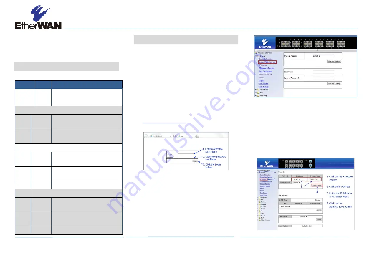
Log in to the management interface:
F.
Change the system name:
-
In the left pane, click
+
next to
System
,
then click
System Name/Password
.
-
On the right side, click in the
System
Name
text box.
-
Replace the name shown with a name you
want to assign to the switch.
-
Click the
Update Setting
button below
the
System Name
text box.
G.
By default there is no password assigned to
the switch. To add a password:
-
In the page above, click in the
Password
text box, enter a password, and retype it
in the
Retype Password
text box.
-
Click
Update Setting
below the
Retype Password
text box.
H.
Change the switch’s IP address and subnet
mask to match the scheme on your network:


