4
08. Start-Up
Expansion vessels are delivered at 4 bars, with pre-
charged factory settings. The pre-charged pressure in
the tank must be adjusted before start-up so that it will
be slightly below the cut-in ( starting ) pressure of the
pump(s). Practical recommended pressure level can
be determined as %10 lower than the cut-in ( starting
) pressure of tank.
08.1 Electrical Connection
The booster sets use single or three-phase motors
sized and powered according to European standards.
The booster set must be connected by a qualified
electrician in compliance with current local electrical
regulations. Ensure that the mains voltage corresponds
to the voltage specified on the booster set rating plate
Before start-up, the grounding of the booster shall be
maintained. The current leakage relay (30 mA) shall
be installed in the pump controller before the energy
supply.
a) Single pump booster sets are supplied as standard
with a thermal magnetic protection switch and float
switch for protection against dry running.
b) Multi-pump booster sets are supplied with control
panels with, main on-off switch, fuse carrier and fuses,
power contactors, overload relays, phase protection
relays over 7,5 KW, electronic change over control
board, float switch for protection against dry running,
automatic-manual switch for each pump power on,
running, reset and no water indicating (warning) lights.
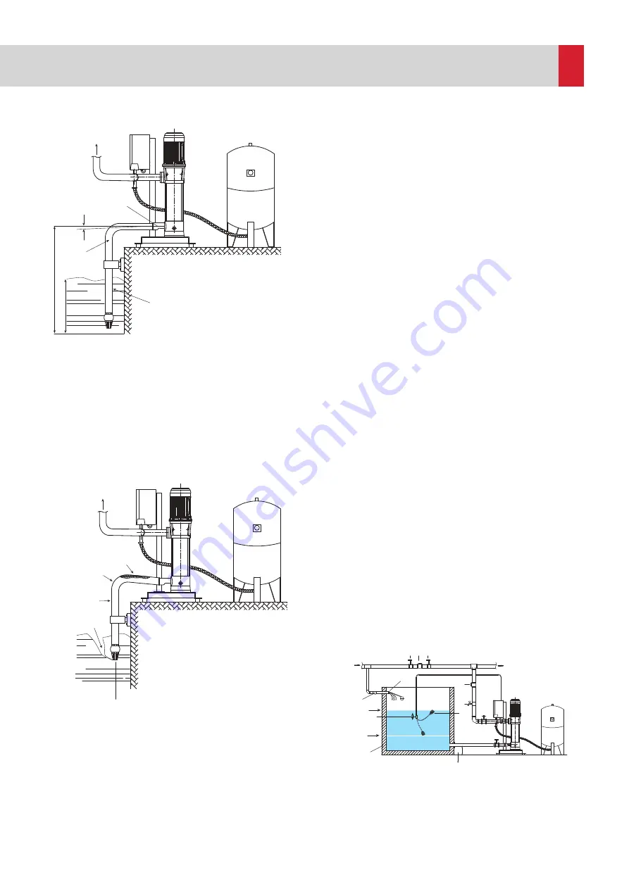
09. Pre-Operation Test
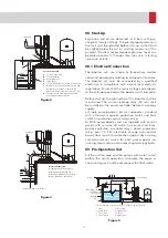
Fill the suction pipe and the pumps with water to test
before the actual operation. Assemble the pipes as
shown in figures 4 and 5 and connect the float switch.
Correct Connection
A -
Eccentric reductions
B -
Positive gradient
C -
Good immersion
D -
Large bends
E -
Suction pipe diameter
≥
Pump port diameter
F -
Difference in lift level referred to pump and
installation. In optimum conditions the
difference in level should not exceed 5-6 m.
G -
The pipe should not weigh on the pump
but on independent supports.
A
3
1
4
2
D
G
F
C
E
B
Installation
Incorrect Connection
1 -
Sharp bend = High head loss
2 -
Insufficient immersion = Air
3 -
Negative gradient = Air pockets
4 -
Pipe diameter < Pump port
Installation
Perpendicular flap or check valve
1 - Valve
2- Check valve
3- Float valve
4- Float switch
5- Service tap
6- Upright valve
7- Strainer
8- Water Tank
1
1
2
2
5
3
4
* The suction pipe should be at least 15 cm above the tank bottom.
*
To the building
Mains
Operating level
Stoppage
Level
Starting-Stop
Level Setting
7
8
Important:
Check valve should not be installed on
the delivery line of the booster sets
with negative suction level. The upright
valve installed on suction also acts like
a check valve.
# A check valve should not be installed on
the delivery line of the plumbing either.
To the building
1
1
2
Mains
6
1
3
4
7
Figure 2
Figure 3
Figure 4
Summary of Contents for EPH B-M46 Series
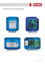
Page 11: ...11 www etna com tr 22 Electric Panels for Single and Double Pump...
Page 33: ...33 www etna com tr NOTES...
Page 34: ...34 NOTES...
Page 35: ...35 www etna com tr NOTES...


