background image

6

The control panel of a fire fighting booster is different 
than the panel of a regular booster. Fire fighting 
boosters are designed to work continuously during 
a fire. Due to the law, these boosters do not include 
thermal protection protecting the electrical engine 
against fire.
Fire fighting boosters run only during fire. Thus, 
there is a weekly test program aiming to minimize 
the possible failures arising from long-term stand-by 
and to detect and intervene to any available failure. 
Fire fighting fighting booster works for a set period 
of time automatically on a set date and time, and 
stop. By ensuring the pumps operate one at a time 
during the time set on the weekly test program, all 
the pumps are operated in order.
If the water level falls below the minimum level in the 
water tank, the device will not be able to supply the 
required pressure and falls down to the calibration 
set pressure (a value just below the operating 
pressure). At this point, an audio and visual alarm 
is activated. Thanks to the electronic circuit. If the 
system demands water from the system during the 
weekly test program, the test ends and the booster 
starts working regularly.

15.2 Installation 

•  Install the fire fighting pump in a humid-free 

environment without the risk of frost and 
explosion, and good ventilation.

•  To keep the temperature constantly above +4 °C 

in the booster room or the booster station, the 
appropriate environment and the tools should 
be provided.

•  The rooms should be large enough to allow 

comfortable entry and exit.

•  If the chamber is below the surface level, stairs 

allowing easy entry and exit should be built. 
(Because it is very important to intervene to the 
failures in cases of emergency.)

•  The room should be well illuminated and the 

room should have a sufficient number of plugs.

•  The fire fighting booster should be placed near 

the water tank or cistern as close as possible. It 
is required for the suction pipe to be short and 
its diameter to be equal to or larger than the 
diameter of the suction pump, and space should 
ensure that the assembly will be made using a 
minimum amount of curves or brackets.

•  Pipe connections (collectors, suction line, delivery 

line) should be arranged in a way that their inlets 
and outlets do not prevent accessing the parts 
required to be accessed during emergencies 
and the control panels., 

•  While placing the fire fighting boosters, it should 

be considered that the engine and/or the pump 

group may be required to be disassembled 
and taken out of the room. (Pipe and collector 
connections should not prevent dismounting 
and removing the pump and/or engine that are 
the other boiler room equipments.)

•  The floor should be inclined enough to allow 

water drainage. If the group chamber is below 
the surface level, the accumulated water should 
be discharged using submerged pump and the 
submerged pump should be backed up.

•  If there is a risk of flood in the chamber, electrical 

control panels should be mounted as high as 
possible. If required, it should be carried to a 
section where there is no such risk.

•  If the control panels are on the chassis of the pump 

group, it should be ensured during assembly that 
the control panel is easily accessible and its cover 
is easily openable (for repair and maintenance).

•  If the control panels are separate from the pump 

group, it should be ensured during assembly 
that the control panel is easily accessible and the 
front panel is directly seen when entered into the 
room.

•  Control panels should be grounded.

16. Jockey Pump in a Booster Unit

The jockey pump in a booster set generally to 

maintain  the small amount of water demands in 
death hours of a day instead of running the main 
pump in a huge plant.

17. Maintenance

The booster sets do not require specific inspections 
at regular intervals. As a precaution, however, we 
recommend that you carry out some or all of the 
following checks at varying intervals depending on 
the operating conditions;

•  Leaks
•  Thermal protector activation 
•  No. of starts per hour
•  Noisy operation

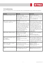
If any malfunctions are found, refer to the next 
section for possible causes and remedies, Check 
membrane tank air pressure regularly every 6 
months (page 7). The pump does not require any 
scheduled routine maintenance. It may require 
extraordinary maintenance which is generally 
cleaning the liquid end or replacing the mechanical 
seal or other worn parts. In this case, please refer to 
the pages 12 - 25.

Summary of Contents for EPH B-M46 Series

Page 1: ...EPH BM CM KO KO ST KI EVS Series Installation Operation Service Maintenance and Spare Parts User Manual...

Page 2: ...uction and Discharge Pipes 3 8 Start up 4 9 Pre Operation Test 4 10 Liquid Level Higher Than the Booster Set or At the Same Level 5 11 Liquid Level Lower Than the Pump Negative Suction 5 12 Checking t...

Page 3: ...ng necessarily visible on the outside hoisting non packed products by securely putting them into a sling from the main chassis Please put the unit on to the floor gently 05 Applications The booster se...

Page 4: ...r control board float switch for protection against dry running automatic manual switch for each pump power on running reset and no water indicating warning lights 09 Pre Operation Test Fill the sucti...

Page 5: ...pressure 14 Operations Description 14 1 Example for two pump sets The starting and stopping of the pumps are determined by the pressure values set on the pressure switches Each pressure switch is conn...

Page 6: ...ount of curves or brackets Pipeconnections collectors suctionline delivery line should be arranged in a way that their inlets and outlets do not prevent accessing the parts required to be accessed dur...

Page 7: ...nd foot valve and the integ rity of the mechanical seal C Reduce the difference in level Use a large diameter pipe Clear the foot valve Replace the foot valve with a larger capacity valve D Invert pow...

Page 8: ...ion Manifold Base Pump Body Valve Electric Motor Frequency Inverter Network Connection Terminal Pressure Transmitter Manometer Discharge Manifold Suction Manifold Base Pump Body Valve Electric Control...

Page 9: ...ents Pump Control Panel Operating level setting Operating Level Stop Level Installation Float switch Water tank Booster Set Electric Control Panel Pump Body Float Switch Base Suction Manifold Discharg...

Page 10: ...340 540 10 7 5 60 100 150 250 410 12 5 9 2 50 80 120 205 330 510 15 11 60 100 170 280 440 17 5 13 90 150 245 385 20 15 80 130 210 330 460 660 25 18 5 100 170 260 370 530 30 22 90 140 220 310 440 35 26...

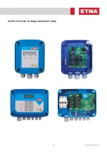
Page 11: ...11 www etna com tr 22 Electric Panels for Single and Double Pump...

Page 12: ...GG22 25 4 Upper Head Flange conta RUBBER SHORE 60A 5 Upper Head GG22 25 6 Nut BRASS 7 O Ring NBR 8 Mechanical Seal CARBON SERAMIC 9 Washer AISI304 10 Upper Diffuser NORYL 11 Fan NORYL 12 Intermediate...

Page 13: ...009 Fan nut 10 011 0066 010 Top diffuser 11 011 0066 011 Impeller fan 12 011 0066 012 Intermediate diffuser 13 011 0066 013 Nut 14 011 0066 014 Spring nut 15 011 0066 015 Self locking bolt 16 011 0066...

Page 14: ...er Head GG22 GG25 1b Upper Head GG22 GG25 2 Coupling Case Plate AISI304 3 Pump Discharge Casing AISI304 4 Mechanical Seal M106K CE EPDM SUS304 5 Coupling Zamak 6 Retaining Ring Shaft Spring AISI304 7...

Page 15: ...L 118 025 0406 002 Jacket KO 4 6 7 6 L 166 025 0407 002 Jacket KO 4 7 7 7 L 190 025 0408 002 Jacket 4 8 7 8 L 214 025 0409 002 Jacket 4 9 L 238 10 019 0000 009 EPH KO 4 7 Retaining Ring Shaft 11 025 0...

Page 16: ...AISI304 3 Pump Discharge Casing AISI304 4 Mechanical Seal M106K CE EPDM SUS304 5 Coupling Zamak 6 Locking Shaft AISI304 7 Shaft AISI420 8 Pump O Ring NBR 9 Jacket AISI304 10 Retaining Ring Shaft AISI...

Page 17: ...08 003 Jacket KO 15 8 L 327 025 2503 003 Jacket KO 25 3 L 137 10 022 1000 007 Retaining Ring Shaft K 10 15 022 2500 011 Retaining Ring Shaft K 25 11 022 1000 002 Diffuser KO 10 15 022 2500 004 Diffuse...

Page 18: ...Air Relief Cock AISI304 4 Mechanical Seal M106K CE EPDM SUS304 5 Coupling Zamak 6 Locking Shaft AISI304 7 Shaft AISI420 8 Head O Ring NBR 9 Jacket AISI304 10 Retaining Ring Shaft AISI304 11 Diffuser...

Page 19: ...O 45 3 L 241 025 4504 001 Jacket KO 45 4 L 313 025 4505 001 Jacket KO 45 5 L 385 025 4506 001 Jacket KO 45 6 L 457 10 025 4500 010 Retaining Ring Shaft K 35 45 11 025 3500 002 Diffuser KO 35 025 4500...

Page 20: ...Galvanized Steel 25 Nut Galvanized Steel 26 Adaptor Cast Iron 1 2 5 6 7 9 10 11 13 12 14 16 17 18 15 20 21 22 23 24 25 1 BASE PLATE CAST IRON 2 MOTOR BRACKET CAST IRON 3 PUMP OUTLET BODY STAINLESS ST...

Page 21: ...L 219mm STAINLESS STELL AISI 420 0240803001 PUMP SHAFT KO ST 8 12 3 L 249mm STAINLESS STELL AISI 420 0240804001 PUMP SHAFT KO ST 8 12 4 L 279mm STAINLESS STELL AISI 420 0240805001 PUMP SHAFT KO ST 8 1...

Page 22: ...009 INLET BODY GASKET KO ST 5 112x 103x1 mm GASKET KLINGERIT 0240800009 INLET BODY GASKET KO ST 8 12 16 142 5x 132 5x1 mm GASKET KLINGERIT 16 0240500011 LOWER SLEEVE KO ST KI 5 STAINLESS STELL AISI 30...

Page 23: ...VANIZED STEEL 0240810002 STUD KO ST 8 12 10 L 480mm GALVANIZED STEEL 0240811002 STUD KO ST 8 12 11 L 510mm GALVANIZED STEEL 0240812002 STUD KO ST 8 12 12 L 540mm GALVANIZED STEEL 0240813002 STUD KO ST...

Page 24: ...AISI 304 23 COUPLING GUARD STAINLESS STEEL AISI 304 24 STUD GALVANIZED STEEL 25 WASHER GALVANIZED STEEL 26 NUT GALVANIZED STEEL KI PUMP PART LIST KI 5 NO PART NAME EXPLANATION 1 Base Plate Cast Iron 2...

Page 25: ...AISI 304 24 STUD GALVANIZED STEEL 25 WASHER GALVANIZED STEEL 26 NUT GALVANIZED STEEL KI PUMP PART LIST KI 8 KI 12 KI 16 KI 20 27 27 ADAPTOR CAST IRON For 132 and 160 Motor body NO PART NAME EXPLANATI...

Page 26: ...0009 INLET DIFFUSER GASKET GASKET KLINGERIT 17 0240500011 BEARING KO ST KI 5 STAINLESS STELL AISI 304 18 0012000019 SINTERED BUSHING SINTER BRONZE 19 0860500003 BODY O RING KI 5 137x2 5mm EPDM 20 0860...

Page 27: ...2 14 L 565mm STAINLESS STELL AISI 420 0860815001 PUMP SHAFT KI 8 12 15 L 595mm STAINLESS STELL AISI 420 0860816001 PUMP SHAFT KI 8 12 16 L 625mm STAINLESS STELL AISI 420 0860817001 PUMP SHAFT KI 8 12...

Page 28: ...304 0860817003 PUMP COVER KI 8 12 17 L 536mm STAINLESS STEEL AISI 304 0860818003 PUMP COVER STAINLESS STEEL AISI 304 0860819003 PUMP COVER KI 8 19 L 596mm STAINLESS STEEL AISI 304 0860820003 PUMP COV...

Page 29: ...2mm GALVANIZED STEEL 0860818002 STUD KI 8 12 18 L 722mm GALVANIZED STEEL 0860819002 STUD KI 8 19 L 752mm GALVANIZED STEEL 0860820002 STUD KI 8 20 L 782mm GALVANIZED STEEL 0861602002 STUD KI 16 20 2 L...

Page 30: ...teel 304 Stainless Steel 304 Stainless Steel 304 Stainless Steel 420 Stainless Steel 304 Stainless Steel 304 Stainless Steel 304 Stainless Steel 304 Stainless Steel 304 Cast Iron Cast Iron NO PART NAM...

Page 31: ...s Steel 304 Stainless Steel 304 Stainless Steel 304 Stainless Steel 304 Stainless Steel 304 Stainless Steel 304 Stainless Steel 304 Stainless Steel 304 Stainless Steel 304 Stainless Steel 304 Stainles...

Page 32: ...ess Steel 304 Stainless Steel 304 Stainless Steel 304 Stainless Steel 304 Stainless Steel 304 Stainless Steel 304 Stainless Steel 304 Stainless Steel 304 Stainless Steel 304 Stainless Steel 420 Stainl...

Page 33: ...33 www etna com tr NOTES...

Page 34: ...34 NOTES...

Page 35: ...35 www etna com tr NOTES...

Page 36: ...Dudullu Organize Sanayi B lgesi 2 Cadde No 14 34775 mraniye stanbul Turkey Tel 90 216 561 47 74 Pbx Fax 90 216 561 47 50 www etna com tr en info etna com tr customer service Rev 10 2021...

Reviews: