4
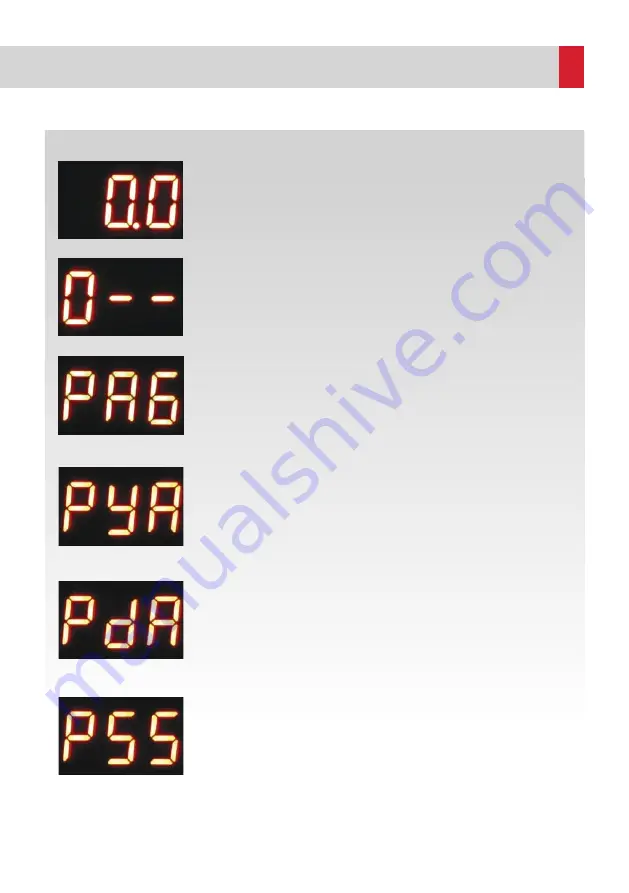
ETNA Electronic Thermal Relay displays '0.0' on the LED screen in the
standby mode when the power is on, as shown on the left-hand side. Green
On LED lights up when 'start' command is given by connecting start inlets
and the LED screen displays the current value.
Password Menu
This screen is displayed when 'set' button is pressed.
This screen requires entering the password to access the parameter setting
menu in order to prevent unauthorized access. The password is entered using
'Up/Down' and 'Set' buttons. Menu password is 132.
a. Error History Program
PAG program is the error history program.
After entering the correct password on the password screen, the PAG program
appears, as shown on the left-hand side. The error history program is accessed
by pressing 'Set’ and the number of the error order is selected using 'Up/Down'
buttons. Pressing 'set’ again displays the respective error code. The most recent
error is always moved to the top of the list. The program is closed by timeout.
b. High Current Limit Program
"PYA" program is the program in which the high current limit is set.
PYA program is accessed by pressing 'Up' button and then 'Set' button is
pressed.
After adjusting the high current limit to the required value using the 'Up/Down'
buttons, 'Set' is pressed once again to save the high current limit value. When
the measured current is over the current limit set in this program, 'High Current
(EYA)' failure is triggered, error LED lights up and error relay is activated.
5. Menu
Figure 2. Main Screen
Figure 3. Password Screen
Figure 4. Error History
Program Screen
Figure 5. High Current Limit
Program Screen
c. Low Current Limit Program
"PdA" program is the program in which the low current limit is set.
PdA program is accessed by pressing 'Up' button and then 'Set' button is
pressed.
After adjusting the low current limit to the required value using the 'Up/Down'
buttons, 'Set' is pressed once again to save the low limit value. When the
measured current is below the current limit set in this program, 'Low Current
(EdA)' failure is triggered, error LED lights up and error relay is activated.
d. Number of Switches Limit Program
"PSS" program is the program in which the maximum number of switches
allowed per hour is set. PSS program is accessed by pressing 'Up' button and
then 'Set' button is pressed. After adjusting the number of switches to the
requested value using the 'Up/Down' buttons, 'Set' is pressed once again to
save the maximum number of switches allowed per hour.
An hour (60 minutes) is divided by the set value to set the time to wait between
2 consecutive starts. For example, if PSS is set to '10' in this program, the
minimum time between starts will be 6 minutes, so a maximum of 10 starts per
hour are possible. The number of switches limit program should be adjusted
according to the power of the electric motor. It can be adjusted between 0 and
80 according to the engine power.
Figure 6. Low Current Limit
Program Screen
Figure 7. Switch Number
Limit Program Screen


