21
MAINTENANCE
Undercarriage
The undercarriage must be visually examined for
broken and missing parts. Check brackets, adjusting
screws and walking beam ends. Replace faulty parts.
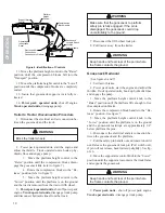
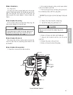
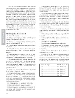
Check the rim clamps or cap nuts for tightness daily.
See Figure 14 for torque specifications and tightening
sequence. Brake drums should be carefully examined
for cracks.
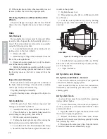
Figure 13. Check Oil Level of Oil Lubricated Bearings.
CAUTION
Do not allow brake drums to become
excessively worn or expensive repairs will be
required.
Figure 14. Tightening Sequence
SERVICE GUIDE-RIDEWELL
SUSPENSIONS
Basic Operation
When properly maintained and operated within de-
sign limits, Ridewell's Monopivot 240 Suspension will
provide many years of trouble-free service. It has sev-
eral unique features which deep maintenance and down-
time to an absolute minimum:
1. A Double-Bonded, manual clamp-in pivot bush-
ing.
2. A patented, contoured weld-on axle seat that re-
quires no U-bolts.
3. A patented eccentric bolt for simple, manual axle
alignment.
4. A longer hanger that minimizes kingpin slap by
improving geometry between pivot bushing and axle
center.
5. A self-contained shock absorber that allows pre-
cise installation and insures proper shock and air spring
tolerances.
Air Springs & Height Control Valve
This air-ride suspension is designed to dampen the
shocks transmitted from road surface to trailer frame
through the Air Springs. The Height Control Valve is
used to maintain the proper ride height from air spring
to chassis (whether empty or loaded) by controlling the
volume of air in the springs.
You may use either a single or dual (leveling) height
control valve system on your trailer. This service manual
addresses the Single Valve System which controls ride
height only. A manual or automatic dump valve may
also be incorporated to exhaust air to prevent "dock
creep" when loading or unloading.
Important Note: The air springs used on the
Monopivot 240 have internal rubber bumpers designed
to carry the trailer load should air spring failure or sud-
den loss of air supply occur. Should an air spring fail
on a "single height control valve system," then all of
the air springs will deflate allowing the suspension to
operate on internal bumpers until repairs can be made.
Should an air spring fail on a "dual height control or
leveling valve system," the springs would deflate on
one side only. Simply deflate the other side by remov-
ing the vertical linkage rod from the valve and rotate
the horizontal lever arm DOWN to fully exhaust the
spring.
ST
EM
CO
HUB
SE
A
L
ADD
FULL
FILL TO THIS LEVEL
Tighten Lug Nuts to recommended
torque using sequence shown
1
1
2
3
4
5
6
7
8
9
10
8
7
6
2
5
3
4
8 Stud Hubs
10 Stud Hubs
Torque Value
3/4" nuts - 180/200 Ft Lb
M22 x 1.5 nuts - 450/500 Ft Lb
1
2
3
4
5

