background image

Fuel Tank

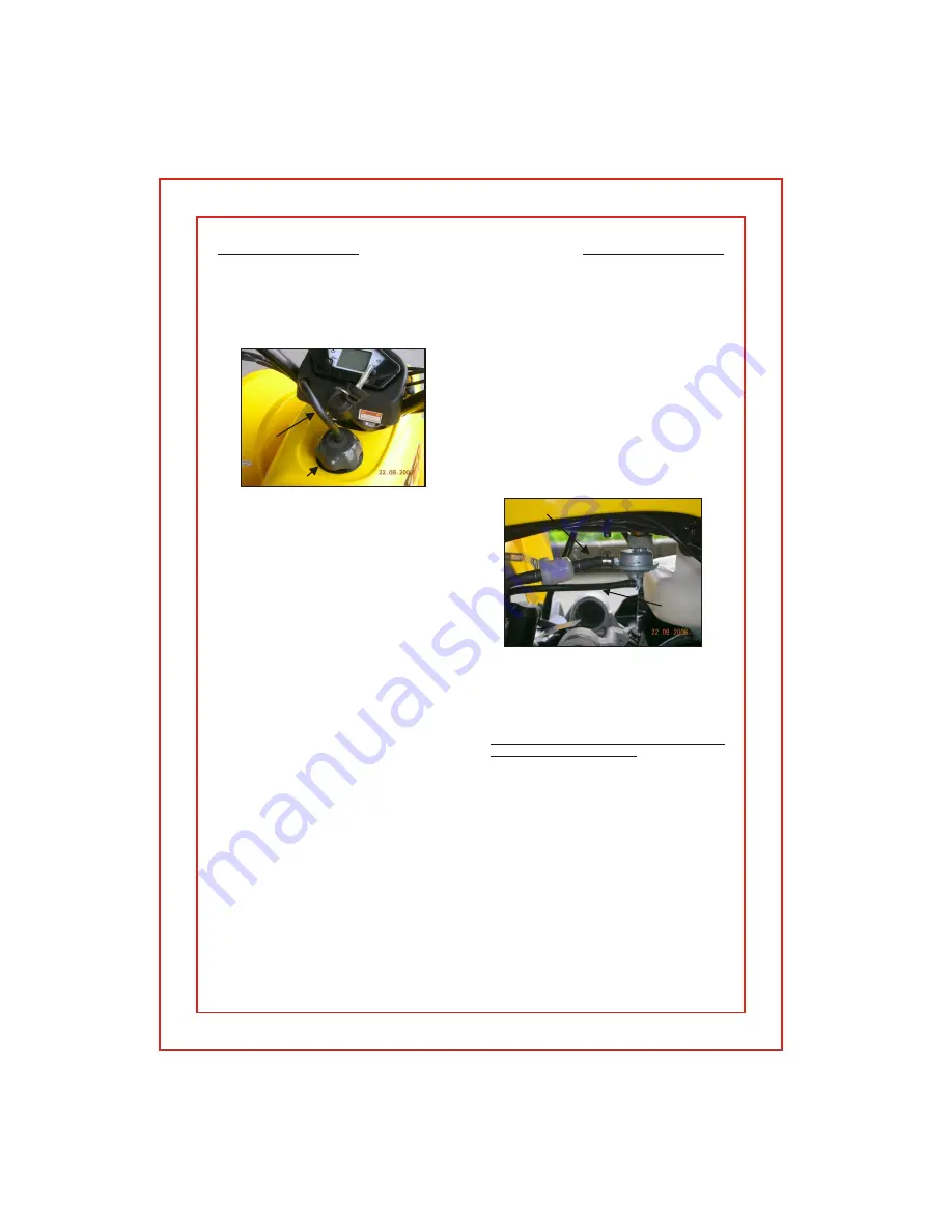
The fuel tank fill cap is located on top of the
unit just ahead of the seat. The cap contains a
vent to prevent a vacuum from forming in the
tank as fuel is used. The vent tube must be
attached to the cap and inserted in the vent
tube holder hole while operating the unit. The

fuel cap vent and vent tube must be clean and
clear of obstructions for the unit to operate
normally. You can check the vent and vent
tube by blowing air through the tube. If you can
not blow through the vent tube and cap you
must clean the vent and tube or replace them.

Every time you refuel your unit, check the
rubber seal inside the cap for cuts, tears and
dirt. Clean or replace the seal if it becomes
worn  or   torn.  The   seal  must   be  in   good
condition to insure a proper seal of the cap to
the tank to prevent fuel spills. DO NOT allow
dirt or other debris to enter the tank when
refueling.

Replace the cap if damaged or if it will not seal
to the tank.

Tighten the cap snugly, being careful not to
over  tighten.  Over  tightening   the  cap  can
cause damage to the cap or seal.

The fuel tank capacity is 9 liters, 2.37 gal,
including a reserve of 1.5 liters, 0.4 gal.

Use unleaded automobile gasoline with an
octane level of 91 or higher.

Your ATV is equipped with a fuel gage located
in the instrument cluster between the  handlebars.

NEVER REFUEL YOUR  ATV when the
engine is HOT.

 Wait 30 minutes after turning

off the unit before refueling. Spilling fuel on a

HOT engine could cause a fire. Wipe up any
fuel spills before re-starting.

Fuel System

To test the fuel valve remove the fuel line from
the carburetor and place the end in a container
to catch the fuel. Insure that your tank has fuel
and press the starter button. Fuel should flow
into the container from the fuel line.

Remember: You can drive further in one hour
on your ATV than you can walk in one day.

ALWAYS CHECK YOUR Fuel level before
you start riding your ATV

The unit is equipped with a vacuum controlled
fuel valve. The fuel supply is automatically shut

The fuel will automatically begin to flow when

Fuel Valve

off when the engine is stopped.

the engine is turned over.

Inline Fuel Filter

Your ATV is equipped with an inline fuel filter
to prevent dirt and debris from entering the
carburetor and engine.

Check the filter for dirt or damage before each
ride and at each refueling. Replace the filter if
dirty or damaged.

DO NOT operate the unit with out a fuel filter.
Doing so can cause damage to the carburetor
and engine.

Page 9

CONTROL FEATURES

CONTROL FEATURES

Fuel Tank Cap

Vent Line

Fuel Line

Vacumn 

Control

 Line

Summary of Contents for EXL-50 - SERVICE

Page 1: ...VER THROTTLE LEVER FUEL SYSTEM FUEL SYSTEM SPEEDOMETER ODOMETER SPEEDOMETER ODOMETER FUEL INDICATOR METER FUEL INDICATOR METER BRAKE CONTROLS BRAKE CONTROLS TIRES AND WHEELS TIRES AND WHEELS Fuel Tank...

Page 2: ...24 24 24 25 25 23 BRAKING SYSTEMS BRAKING SYSTEMS THROTTLELEVER THROTTLELEVER DRIVE CHAIN DRIVE CHAIN ELECTRICAL BATTERY ELECTRICAL BATTERY Front Brake System Inspection Front Brake Adjustment Rear B...

Page 3: ...the E TON manufacturer s warranty Riders must thoroughly read this manual and must fully understand its contents b efore r iding All riders should enroll in an ATV Rider Safety Course Your E TON deale...

Page 4: ...tification Number VIN is located at the front of the unit under the front fender on a plate mounted between the main frame rails Engine serial number is located on the left hand side of the engine on...

Page 5: ...eadlight Rear position lamp switch 12 Horn button 13 Start button 14 Direction indicator switch Parking indicator switch Controls Switches Feature Locations for ViperST Locations of controls and featu...

Page 6: ...4 Direction indicator switch 15 Fuel indicator meter Transmission gear selector Parking indicator switch Controls Switches Feature Locations for YukonST Locations of controls and features 1 Fuel tank...

Page 7: ...reduce your pressure on the lever and the spring tension will automatically reduce your speed To increase the throttle s travel thus increasing the maximum speed turn the throttle stop bolt counter cl...

Page 8: ...caution not to apply too much pressure to your front brakes so that the wheels lock up stop turning and causing a loss of steering control If the front wheels lock up and stop turning lightly reduce t...

Page 9: ...ine with an octane level of 91 orhigher YourATV is equipped with a fuel gage located in the instrument cluster between the handlebars NEVER REFUEL YOUR ATV when the engine is HOT Wait 30 minutes after...

Page 10: ...your tires and wheels for damage and wear before each riding session Inspect each tire for cuts tears and punctures Inspect the wheel rim for dents and separation of the wheel from the tire bead Repla...

Page 11: ...power on and off 2 Fuel indicator to F when the tank is full and to E when empty The theoil gauge flashes when 3 4 stages left 3 The direction indicator switch is on the left handlebar push to right o...

Page 12: ...elector switch Always pause in the N neutral positon for a few seconds when shifting from forward to revers or from revers to forward this allows thetransmissiontime todisengageand resycronize Transmi...

Page 13: ...le air cooled 49 3cc 50 0 42 0mm 7ps 7500rpm Automatic C V T V Belt 1670mm 65 8 940mm 37 0 1040mm 41 0 1110mm 43 7 152kg 3351b SingleA arm AdjustableShocks SwingArm AdjustableShock Dual Mechanical dru...

Page 14: ...octane 4 5 liters 1 2 gal 1 0 liters 1gt SAE 80 90 weight 300cc 10 2oz BPR7HS W22FRP U QL82YC 0 6 0 7mm 0 023 High grade synthetic 2 cycle injector oil JASO FC Grade 12V 4AH 5AH GTX5L 19 teeth 34 tee...

Page 15: ...ng Transmission Oil 1 Place an oil catch pan under the unit directly below the transmission box 2 Remove the transmission box drain plug located on the bottom of the transmission box on the underside...

Page 16: ...element in clean engine oil until completely saturated 3 Squeeze out the excess oil until the element does not drip any oil 4 Allow the element to dry then reinstall the element and cover C V T Filte...

Page 17: ...taining the correct adjustment insure that the locking nut is tightened securely against the adjusting wheel to prevent the adjustment wheel from turning due to vibration Keep your brake cables lubric...

Page 18: ...rakes are applied check your fluid level and brake pads If the brake lever feels spongy or does not stop when squeezed you may have air in the lines All air must be purged from the brake lines for the...

Page 19: ...electrical power to the unit The battery is a 12 volt jell acid type that contains no liquid electrolyte The battery should be removed from the vehicle when stored for extended periods and charged be...

Page 20: ...the throttle will return to the idle position automatically ThrottleLever Adjusting the throttle cable The cable should be adjusted to allow for free travel before the throttle engages the carburetor...

Page 21: ...nut to take up the excess slack inthechain Oncethechainhas beenadjustedto the proper tension retightenthe axle position locking bolt Inspect the drive and axlesprockets for worn damaged or broken tee...

Page 22: ...e I L I R Inspect as part of pre ride inspection Inspect as part of pre ride inspection of pre ride inspection Inspect as part Replace every 2 years Inspect as part of pre ride inspection Inspect as p...

Page 23: ...go gently Do not run at high speeds Do not approach the maximum RPMs during the break in period Failing to adequately break in your E TON ATV will decrease the long term power and life of the engine...

Page 24: ...ing may cause the front wheels to slide straight ahead If this happens back off the throttle and Stop To keep from skidding on slippery terrain avoid braking or accelerating until you have regained di...

Page 25: ...pendable maintenance items made in connection with required maintenance services including but not limited to coolant spark plugs gaskets belts filters lubricants and hoses In addition this warranty d...

Page 26: ...WIRING DIAGRAM Page 26 VIPER Wiring Diagram...

Page 27: ...WIRING DIAGRAM YUKON Wiring Diagram...

Page 28: ...conditions that are specifically excluded from this warranty program are 1 Damage caused by accidents misuse negligence improper vehicle operation 2 Any modification or alteration to any standard spec...

Page 29: ...in proper operatingcondition The dealer is responsiblefor checking and performing all items on the set up and pre delivery checklist prior to delivery to the customer This warranty isvalid at anyautho...

Page 30: ...Owner s Notes Page 30...

Page 31: ...Page 31...

Page 32: ...Page 32 Page 31...

Reviews: