background image


10 

ITX-E8 User`s Manual 

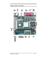
Jumpers on the ITX-E8 


The jumpers on the ITX-E8 allow you to configure your Main Board 
according to the needs of your applications. If you have doubts about 
the best jumper configuration for your needs, contact your dealer or 
sales representative. The following table lists the jumpers on ITX-E8 
and their respective functions. 


Jumper Locations on the ITX-E8 ......................................  11 
JP1: LCD PANEL Power Selection ................................... 12  
JP2, JP3: On-Board LAN Enable/Disable selection .......... 12  
JP4, JP8: COM Power Selection ........................................ 12  
JP5: CF Card Mode Selection ............................................ 13  
JP6: Clear CMOS RAM Data ............................................ 13  
JP7: COM6 Power Pin(Pin9) ............................................. 13  
AT_MODE: AT Mode Selection ....................................... 14 
PWRMODE: AT Mode Selection...................................... 14 
COM2MODE1 & COM4MODE1: RS232/RS422/RS485 
Protocal Selection............................................................... 15  


Summary of Contents for ITX-E8

Page 1: ...I IT TX X E E8 8 INDUSTRIAL MOTHERBOARD User s Manual Version 1 0...

Page 2: ...ll the original manufacturer be liable for direct indirect special exemplary incidental incidental or consequential damages resulting from any defect or omission in this manual even if advised of poss...

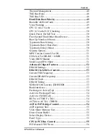
Page 3: ...P6 Clear CMOS RAM Data 13 JP7 COM6 Power Pin Pin9 13 AT_MODE AT Mode Selection 14 PWRMODE AT Mode Selection 14 COM2MODE1 COM4MODE1 RS232 RS422 RS485 Protocol Selection 15 Connectors on the ITX E8 16 C...

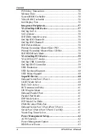
Page 4: ...tion 37 Starting Setup 37 Using Setup 38 Getting Help 39 In Case of Problems 39 Main Menu 40 Standard CMOS Features 40 Advanced BIOS Features 40 Advanced Chipset Features 41 Integrated Peripherals 41...

Page 5: ...sion Control For OS 51 OS Select For DRAM 64MB 51 Video BIOS Shadow 51 Small Logo EPA Show 51 Advanced Chipset Features 52 DRAM Settings 52 DRAM Clock Drive Control 53 Current FSB Frequency 53 Current...

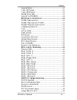
Page 6: ...58 VIA OnChip PCI Device 59 VIA 3058 AC97 Audio 59 OnChip USB Controller 59 OnChip EHCI Controller 59 USB Emulation 59 USB Keyboard Support 60 USB Mouse Support 60 SuperIO Device 60 Onboard Serial Por...

Page 7: ...65 Modem Ring Resume 65 RTC Alarm Resume 65 Date of Month 66 Resume Time hh mm ss 66 IRQs Activity Monitoring 66 Primary INTR 66 IRQ3 COM 2 66 IRQ4 COM 1 66 IRQ5 LPT 2 67 IRQ6 Floppy Disk 67 IRQ7 LPT...

Page 8: ...core 1 5V 3 3V 5V 12V 12V VBAT 5VSB Voltages 71 Shutdown Temperature 71 CPU FAN Control 71 SYSTEM FAN Control 71 Frequency Voltage Control 72 CPU Clock Ratio 72 Spread Spectrum 72 Load Fail Safe Defau...

Page 9: ...l 1 Introduction This manual is designed to give you information on the ITX E8 Mini ITX MainBoard The topics covered in this manual are as follows Features Specification Jumper setting and Connectors...

Page 10: ...2 ITX E8 User s Manual Chapter 1 Features Specifications Features 3 Specifications 4...

Page 11: ...th LCD Brightness control by software Software ready for Windows XP 2K Dual 10 100 1000M LAN Design with Remote Boot and Wake Up on LAN support AC97 3D Audio Codec on board with internal connection fo...

Page 12: ...Pins D Sub Female connector for CRT Displays One 40 pins connector for Dual 18 24 bits LVDS LCD displays One 5 pins JST connector for Inverter power and brightness control Super I O Winbond 83627HF LP...

Page 13: ...col PIDE and SATA PIDE controller build in VT8237 support up to UltraDMA mode 6 or ATA133 speed One standard 40 pins box header to support 3 5 HDD CDROM DVD player or DOM Flash Disk One standard 44 pi...

Page 14: ...ashROM with BootBlock for Fail safe BIOS utility for field update VBIOS for LCD panel support and LAN remote BootROM integrated Power Connector Support both AT mode or ATX mode operation One ATX 20 pi...

Page 15: ...ITX E8 User s Manual 7 Others One Buzzer 9mm on board for beep message Operating Temperature 0 50 C Operation Rage Relative Humility 5 95 non condensing Dimensions 170mm W x 170mm L...

Page 16: ...8 ITX E8 User s Manual This page is intentionally left blank...

Page 17: ...ITX E8 User s Manual 9 Chapter 2 Jumper setting Connectors Jumpers on the ITX E8 10 Connectors on the ITX E8 16...

Page 18: ...sales representative The following table lists the jumpers on ITX E8 and their respective functions Jumper Locations on the ITX E8 11 JP1 LCD PANEL Power Selection 12 JP2 JP3 On Board LAN Enable Disab...

Page 19: ...ITX E8 User s Manual 11 Jumper Locations on the ITX E8...

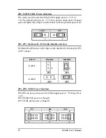
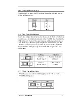
Page 20: ...mper to make Panel work in specified power rail 3 3V 5V JP2 JP3 On Board LAN Enable Disable selection On Board Fast Ethernet LAN chips can be disabled by shorting the JP2 or JP3 jumper Port Enable Dis...

Page 21: ...in the CMOS RAM To clear the CMOS data 1 Turn off the system power 2 Remove Jumper cap from pin1 2 3 Short the pin2 and pin3 for three seconds 4 Put Jumper cap back to pin1 2 5 Turn on your computer...

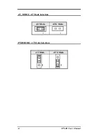
Page 22: ...14 ITX E8 User s Manual AT_MODE AT Mode Selection AT Mode ATX Mode 1 1 PWRMODE AT Mode Selection AT Mode ATX Mode...

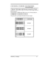
Page 23: ...and RS485 while COM1 COM3 COM5 and COM6 support diffused RS232 protocol The Protocols of COM2 and COM4 can be set up through jumpers COM2MODE1 COM2 Protocols selection COM4MODE1 COM4 Protocols selecti...

Page 24: ...Connector 20 EIDE Connectors 21 COM1 Serial Port 23 COM2 Serial Port 23 COM3 Serial Port 24 COM4 Serial Port 24 COM5 Serial Port 25 COM6 Serial Port 25 LPT Port 26 PS 2 Keyboard Mouse Connector 27 VGA...

Page 25: ...ITX E8 User s Manual 17 Connector Locations on the ITX E8 1 2...

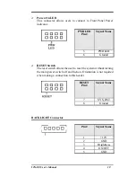
Page 26: ...utton This 2 pin connector acts as the Power Supply On Off Switch on the ITX E8 main board When pressed the switch will force the Main board to power on When pressed again it will force the main board...

Page 27: ...ame 5 PWRLED 6 Ground RESET Switch The reset switch allows the user to reset the system without turning the main power switch off and then on Orientation is not required when making a connection to th...

Page 28: ...IRRX 5V GND FIR IrDA Pin Signal Name 1 5V 2 FIR 3 Ir RX 4 Ground 5 Ir TX DIO Connector DIO port supports 8 digital I O bits Each bit can be configured as Input or output individually All bits are 5V t...

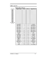
Page 29: ...ost data 11 Host data 3 11 12 Host data 12 Host data 2 13 14 Host data 13 Host data 1 15 16 Host data 14 Host data 0 17 18 Host data 15 Ground 19 20 Key DRQ0 21 22 Ground Host IOW 23 24 Ground Host IO...

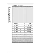
Page 30: ...a 4 9 10 Host data 11 Host data 3 11 12 Host data 12 Host data 2 13 14 Host data 13 Host data 1 15 16 Host data 14 Host data 0 17 18 Host data 15 Ground 19 20 Key DRQ1 21 22 Ground Host IOW 23 24 Grou...

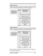
Page 31: ...ady 7 RTS Request to send 8 CTS Clear to send 9 5V Ring IN or 12V COM2 Serial Port COM2 a 10 pins header connector is the onboard COM2 serial port of the ITX E8 The following table shows its pin assig...

Page 32: ...set ready 7 RTS Request to send 8 CTS Clear to send 9 Ring IN 10 N C COM4 Serial Port COM4 a 10 pins header connector is the onboard COM4 serial port of the ITX E8 The following table shows its pin as...

Page 33: ...ready 7 RTS Request to send 8 CTS Clear to send 9 Ring IN 10 N C COM6 Serial Port COM6 a 10 pins header connector is the onboard COM6 serial port of the ITX E8 The following table shows its pin assig...

Page 34: ...le connector It can be configured as EPP or ECP or SPP mode Signal Name Pin Pin Signal Name Strobe 1 2 DATA0 DATA1 3 4 DATA2 DATA3 5 6 DATA4 DATA5 7 8 DATA6 DATA7 9 10 ACK BUSY 11 12 PE SLCT 13 14 AUT...

Page 35: ...d and Mouse connector Pin Signal Name 1 Keyboard Mouse data 2 NC 3 GND 4 5V 5 Keyboard Mouse clock 6 GND VGA Connector The pin assignments of VGA CRT connector are as follows Signal Name Pin Pin Signa...

Page 36: ...below Signal Name Pin Pin Signal Name RED 1 2 GND GREEN 3 4 GND BLUE 5 6 GND HSYNC 7 8 DDC_DATA VSYNC 9 10 DDC_CLK INT_KBMS Connector INT_KBMS is for internal input devices or MSR connection The pin o...

Page 37: ...The ATX 20P power connector supplies power to the whole Main board Pin Signal Name 1 3 3V 2 3 3V 3 GND 4 VCC 5 GND 6 VCC 7 GND 8 Power Good 9 5VSB stand by 5V 10 12V 11 3 3V 12 12V 13 GND 14 PS_ON sof...

Page 38: ...power connector is not connected the system will not start Pin Signal Name 1 GND 2 GND 3 12V ATX_12V 4 12V CPU Fan Power Connector This is a 3 pins header for the CPU fan 3 2 1 Pin Signal Name 1 Grou...

Page 39: ...gnal Name 1 7 1 GND 2 SATARX 3 SATARX 4 GND 5 SATATX 6 SATATX 7 GND USB12 USB34 Connectors The following table shows the pin outs of the USB12 USB34 connectors Signal Name Pin Pin Signal Name N C 1 2...

Page 40: ...ve a standard USB interface Also make sure your OS supports USB controller If your OS does not support USB controller please contact OS vendor for possible patch or driver upgrade For more information...

Page 41: ...n Dual color LED on the left hand side indicates the operation mode i e 10Base T 100Base T or 1000Base T LNK ACT STATUS ON Link OFF Disconnected FLASH Packets TX RX SPEED MODE ORANGE 1000 Mbps GREEN 1...

Page 42: ...3 GND 4 GND 5 LINEOUT L 6 LINEOUT R 7 GND 8 GND 9 MIC1 IN 10 MIC2 IN 11 CENTER OUT 12 LFE OUT 13 SURR OUTL 14 SURR OUTR CD_IN Connector CD_IN connector is designed for wire the CD_ROM audio signals t...

Page 43: ...V GND 3 4 GND LCDVDD 5V 3 3V 5 6 LCDVDD 5V 3 3V GND 7 8 GND BRIGHTNES 9 10 BCKLITE_ON LVDS_GND 11 12 LVDS_GND CHA_TX0 13 14 CHB_TX0 CHA_TX0 15 16 CHB_TX0 LVDS_GND 17 18 LVDS_GND CHA_TX1 19 20 CHB_TX1...

Page 44: ...this chapter are as follows BIOS Introduction 37 Main Menu 40 Standard CMOS Setup 42 Advanced BIOS Features 47 Advanced Chipset Features 52 Integrated Peripherals 57 Power Management Setup 62 PnP PCI...

Page 45: ...ntended to guide you through the process of configuring your system using Setup Starting Setup The AwardBIOS is immediately activated when you first power on the computer The BIOS reads the system inf...

Page 46: ...nges Submenus Exit Current page to the next higher level menu Move Enter Move to the item you desired PgUp key Increase the numeric value or make changes PgDn key Decrease the numeric value or make ch...

Page 47: ...o longer is able to boot the AwardBIOS supports an override to the CMOS settings which resets your system to its defaults The best advice is to only alter settings that you thoroughly understand To th...

Page 48: ...Peripherals Power Management Setup PnP PCI Configurations PC Health Status Frequency Voltage Control Load Fail Safe Defaults Load Optimized Defaults Set Supervisor Password Set User Password Save Exi...

Page 49: ...tage Control Use this menu to specify your settings for frequency voltage control Load Fail Safe Defaults Use this menu to load the BIOS default values for the minimal stable performance for your syst...

Page 50: ...OS CMOS Setup Utility Standard CMOS Features Date mm dd yy Mon Feb 8 2004 Time hh mm ss 16 19 20 IDE Channel 0 Master None IDE Channel 0 Slave None IDE Channel 1 Master None IDE Channel 1 Slave None D...

Page 51: ...b menu of detailed options IDE Channel 1 Slave Options are in its sub menu Press Enter to enter the sub menu of detailed options Drive A Drive B None 360K 5 25 in 1 2M 5 25 in 720K 3 5 in 1 44M 3 5 in...

Page 52: ...to the main menu Use the Table listed below to configure the hard disk Phoenix AwardBIOS CMOS Setup Utility IDE Channel 0 Master IDE HDD Auto Detection Press Enter IDE Channel 0 Master Auto Access Mo...

Page 53: ...apacity Auto Display your disk drive size Disk drive capacity Approximated Note that this size is usually slightly greater than the size of a formatted disk given by a disk checking program Access Mod...

Page 54: ...e CGA 80 Power up in 80 column mode MONO For Hercules or MDA adapters Halt On This field determines whether the system will halt if an error is detected during power up All errors Whenever the BIOS de...

Page 55: ...Boot Device Hard Disk Third Boot Device USB FDD Boot Other Device Enabled Boot Up NumLock Status Off Typematic Rate Setting Disabled x Typematic Rate Chars Sec 6 x Typematic Delay Msec 250 Security O...

Page 56: ...efault which means the board will wait 16 minutes before it activates the processor s integrated thermal control circuit The choice 4 Min 8 Min 16 Min 32 Min Thermal Management The CPU Thermal Managem...

Page 57: ...ESC to exit this menu Virus Warning Allows you to choose the VIRUS Warning feature for IDE Hard Disk boot sector protection If this function is enabled and someone attempt to write data into this are...

Page 58: ...120 Hard Disk ZIP100 CDROM Disabled Enabled USB FDD USB ZIP USB CDROM Legacy LAN Boot Up NumLock Status Selects power on state for NumLock The choice On Off Typematic Rate Setting Keystrokes repeat at...

Page 59: ...security select PASSWORD SETTING at Main Menu and then you will be asked to enter password Do not type anything and just press Enter it will disable security Once the security is disabled the system w...

Page 60: ...m memory resources such as DRAM and the external cache It also coordinates communications between the conventional ISA bus and the PCI bus It must be stated that these items should never need to be al...

Page 61: ...ive to Precharge Tras 05T X Active to CMD Trcd 4T X REF to ACT REF Trfc 21T X ACT 0 to ACT 1 TRRD 3T Item Help Menu Level Move Enter Select PU PD Value F10 Save ESC Exit F1 General Help F5 Previous Va...

Page 62: ...ACT 1 TRRD The choice 3T AGP P2P Bridge Control Phoenix AwardBIOS CMOS Setup Utility AGP P2P Bridge Control AGP Aperture Size 128M VGA Share Memory Size 64M Direct Frame Buffer Enabled Select Display...

Page 63: ...T LCD TV DVI HDTV CRT LCD CRT TV CRT DVI CRT HDTV DVI HDTV LCD DVI TV DVI Panel Type The choice Min 0000 Max 000F Key in HEX number CPU PCI Bus Control Phoenix AwardBIOS CMOS Setup Utility CPU PCI Bus...

Page 64: ...This makes memory from 15MB and up unavailable to the system Expansion cards can only access memory up to 16MB The default of this field is set to Disabled The choice Disabled 15M 16M System BIOS Cach...

Page 65: ...U PD Value F10 Save ESC Exit F1 General Help F5 Previous Values F6 Fail safe Defaults F7 Optimized Defaults VIA OnChip IDE Device Phoenix AwardBIOS CMOS Setup Utility VIA OnChip IDE Device OnChip SATA...

Page 66: ...oice Enabled Disabled IDE Prefetch Mode The choice Enabled Disabled Primary Secondary Master Slave PIO The choice Auto Mode 0 Mode 1 Mode 2 Mode 3 Mode 4 Primary Secondary Master Slave UDMA The choice...

Page 67: ...ue F10 Save ESC Exit F1 General Help F5 Previous Values F6 Fail safe Defaults F7 Optimized Defaults VIA 3058 AC97 Audio The choice Auto Disabled OnChip USB Controller The choice All Disabled All Enabl...

Page 68: ...X RxD TxD Active Hi Lo X IR Transmission Delay Enabled X UR2 Duplex Mode Half Onboard Parallel Port 378 IRQ7 Parallel Port Mode SPP X EPP Mode Select EPP1 7 X ECP Mode Use DMA 3 Item Help Menu Level M...

Page 69: ...ss you are certain your hardware and software both support one of the other available modes The choice SPP EPP ECP ECP EPP Normal EPP Mode Select Select EPP port type 1 7 or 1 9 The choice EPP1 7 1 9...

Page 70: ...Management Option User Define HDD Power Down Disable Suspend Mode Disable Video off Option Suspend Off Video off Method V H SYNC Blank MODEN Use IRQ 3 Soft Off by PWR BTTN Instant Off IRQ Event Activi...

Page 71: ...r management Suspend Mode 1 hr and HDD Power Down 15 min Max Power Saving Maximum power management Suspend Mode 1 min and HDD Power Down 1 min User Define Allows you to set each mode individually The...

Page 72: ...Off by PWRBTN The choice Instant Off Delay 4 Sec IRQ Event Activity Detect Phoenix AwardBIOS CMOS Setup Utility IRQ Event Activity Detect PS2KB Wakeup Select Hot key PS2KB Wakeup from S3 S4 S5 Disabl...

Page 73: ...Ctrl F6 Ctrl F7 Ctrl F8 Ctrl F9 Ctrl F10 Ctrl F11 Ctrl F12 Power Wake Any Key PS2MS Wakeup from S3 S4 S5 The choice Enabled Disabled USB Resume from S3 The choice Enabled Disabled VGA The choice OFF O...

Page 74: ...Enabled IRQ7 LPT 1 Enabled IRQ8 RTC Alarm Disabled IRQ9 IRQ2 Redir Disabled IRQ10 Reserved Disabled IRQ11 Reserved Disabled IRQ12 PS 2 Mouse Enabled IRQ13 Corpocessor Enabled IRQ14 Hard Disk Enabled...

Page 75: ...Q8 RTC Alarm The choice Enabled Disabled IRQ9 IRQ2 Redir The choice Enabled Disabled IRQ10 Reserved The choice Enabled Disabled IRQ11 Reserved The choice Enabled Disabled IRQ12 PS 2 Mouse The choice E...

Page 76: ...nter PCI VGA Palette Snoop Disabled Assign IRQ For VGA Enabled Assign IRQ For USB Enabled Item Help Menu Level Select Yes if you are using a Plug and Play capable operating system Select No if you nee...

Page 77: ...pe depending on the type of device using the interrupt This item allows you to determine the IRQ assigned to the ISA bus and is not available to any PCI slot Legacy ISA for devices compliant with the...

Page 78: ...nt CPUFAN Speed 6308 RPM Current SYSFAN Speed 0 RPM Vcore 1 12V 1 5V 1 53V 3 3V 3 48V 5V 5 21V 12V 12 46V 12V 11 62V VBAT V 3 37V 5VSB V 5 18V Shutdown Temperature Disabled CPU FAN Control Enabled SYS...

Page 79: ...AN Speed Shows SYSFAN speed Vcore 1 5V 3 3V 5V 12V 12V VBAT 5VSB Voltages Shows Power rails voltage Shutdown Temperature The choice Disabled 60 C 140 F 65 C 149 F 70 C 158 F 75 C 167 F CPU FAN Control...

Page 80: ...ntrol CPU Clock Ratio 15 X Spread Spectrum Enabled Item Help Menu Level Move Enter Select PU PD Value F10 Save ESC Exit F1 General Help F5 Previous Values F6 Fail safe Defaults F7 Optimized Defaults C...

Page 81: ...ults Y N N Pressing Y loads the BIOS default values for the most stable minimal performance system operations Load Optimized Defaults When you press Enter on this item you get a confirmation dialog bo...

Page 82: ...abort the selection and not enter a password To disable a password just press Enter when you are prompted to enter the password A message will confirm the password will be disabled Once the password i...

Page 83: ...n your system off The next time you boot your computer the BIOS configures your system according to the Setup selections stored in CMOS After saving the values the system is restarted again Exit Witho...

Page 84: ...76 ITX E8 User s Manual CHAPTER 4 Appendix I O Port Address Map 77 Interrupt Request Lines IRQ 78 POST Beep 79...

Page 85: ...Fh Interrupt Controller 1 040h 05Fh Timer 060h 06Fh Keyboard Controller 070h 07Fh Real Time Clock NMI 080h 09Fh DMA Page Register 0A0h 0BFh Interrupt Controller 2 0C0h 0DFh DMA Controller 2 0F0h Clear...

Page 86: ...he following table shows the IRQ used by the devices on the Industrial CPU Card Level Function IRQ0 System Timer Output IRQ1 Keyboard IRQ2 Interrupt Cascade IRQ3 Serial Port 2 IRQ4 Serial Port 1 IRQ5...

Page 87: ...that a video error has occurred and the BIOS cannot initialize the video screen to display any additional information This beep code consists of a single long beep followed by two short beeps The othe...

Reviews: