Chapter3 BIOS Configuration
PISA-E1 User’s Manual
21
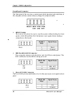
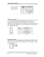
ATX Power ON/OFF Button
This 2-pin connector acts as the “Power Supply On/Off Switch” on the SBC
card. When pressed, the switch will force the SBC card to power on. When
pressed again, it will force the SBC card to power off.
1
PWR BTN
Pin #
Signal Name
Power
7 PWR-BTN
Button
8 GND
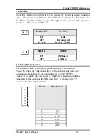
CPU Fan Power Connector
This is a 3-pin header for the CPU fan. The fan must be a 12V fan.
1 2 3
Pin #
Signal Name
1
Rotation
2
+12V
3
Ground
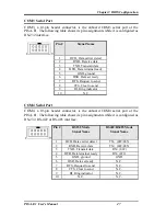
USB Connectors
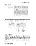
The following table shows the pin outs of the USB connectors.
6
7
8
9
10
1
2
3
4
5
USB1
Pin#
USB0
Pin #
Signal Name
10 1
+5V
9 2 USB-
8 3 USB+
7 4 Ground
6 5 N.C.


