Chapter3 BIOS Configuration
PISA-E1 User’s Manual
29
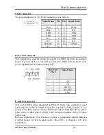
VGA Connector
The pin assignments of VGA CRT connector are as follows:
Signal Name
Pin
Pin
Signal Name
Red
1
2
Green
Blue
3
4
N.C.
GND
5
6
GND
GND
7
8
GND
N.C.
9
10
GND
N.C.
11
12
N.C.
HSYNC
13
14
VSYNC
NC
15
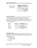
ISO_CAN Connector
This connector is used for wiring the generic CANBUS signal to an isolation
board. If you decide to use on-board non-isolated CANBUS driver, please short
pin3-4 together with a 2.54mm jumper cap.
+5V RX GND
1
TX RX-OUT
ISO_CAN
Pin #
Signal Name
1 +5V
2 TX
3 RX_IN
4 RX_OUT
5 GND
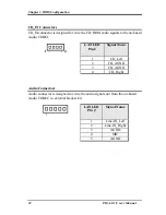
CANBUS Connector
There is CANBUS driver integrated on PISA-E1 board. This connector is used
for wiring the buffered CANBUS signal to external CAN BUS board. If you
decide to use this connector and on-board non-isolated CANBUS driver, please
make sure you short pin3-4 of ISO_CAN connector together with a 2.54mm
jumper cap.
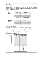
In some applications, it is necessary to have a termination resistor between
CANbus signals for better signal quality. Short JP11, will apply a 124 ohm
termination.

