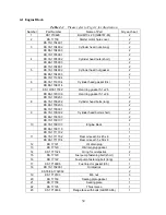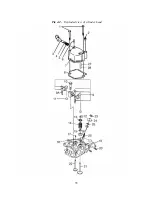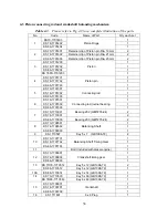
4.2 Cylinder head Assembly
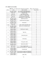
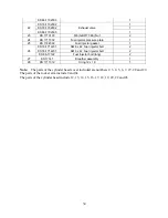
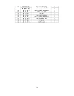
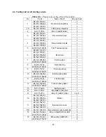
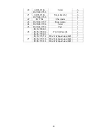
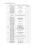
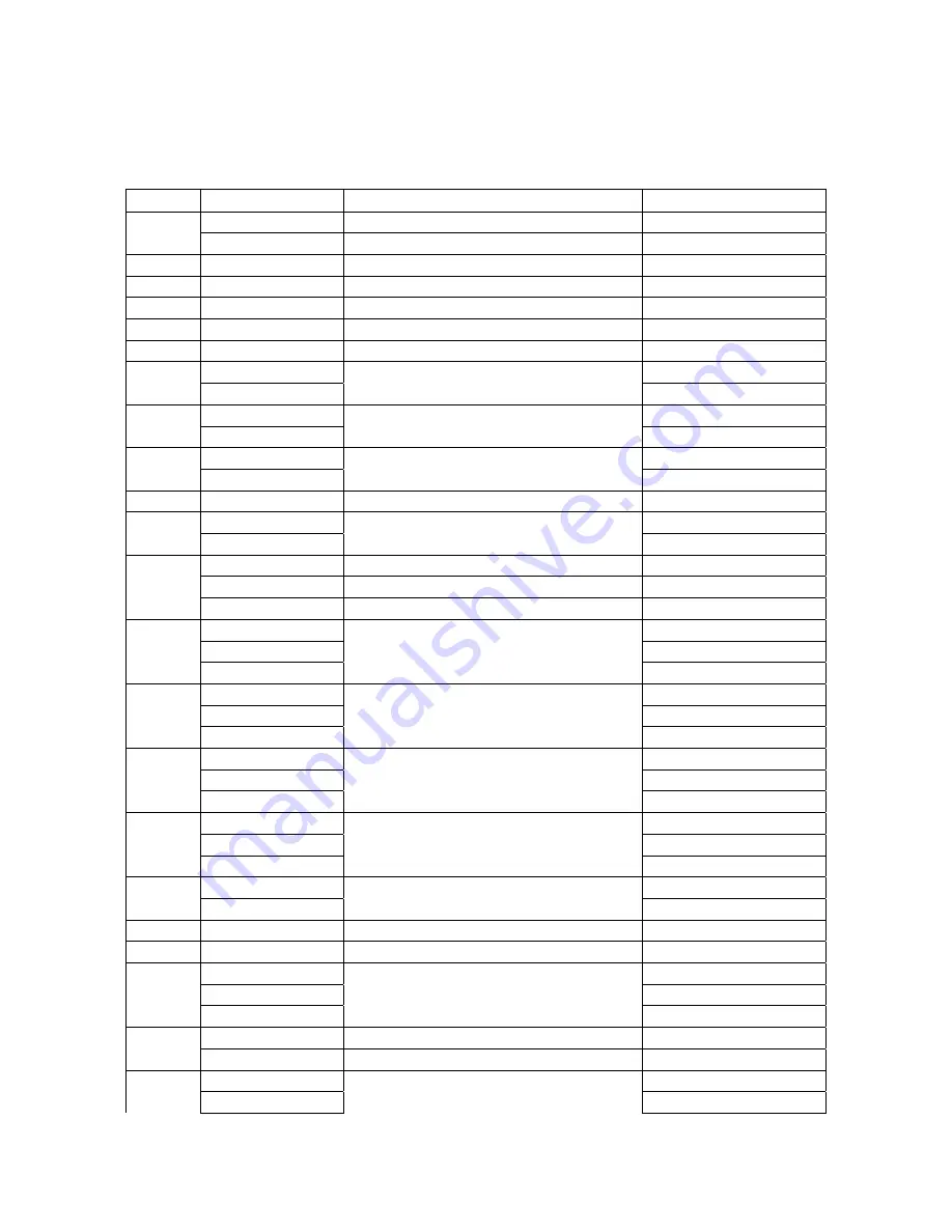
Table 4-2. Part listing for cylinder head assembly. Please refer to Fig 4-2
No.
Code
Names of Parts
Qty each set
KS 70/78-1710755
M6 x 55 Flanged Bolt (GB5789-86)
2
1
KS 86-1710730
M6 x 70 Flanged Bolt (GB5789-86)
2
2
KS 17142
Oiling hole plug
1
3
KS 17139
Decompression shaft
1
4
KS 1711310
O ring 10 x 1.9 (GB1235-76)
1
5
KS 17140
Decompression shaft spring
1
6
KS 1711103
Retaining pin 3 x 16 (GB119-86)
1
KS 70/78-17066
1
7
KS 86-1706603
Cylinder head cover
1
KS 70/78-17170
1
8
KS 86-1717001
Cylinder head cover gasket
1
KS 70/78-17168
1
9
KS 86-1716801
Rocker arm
1
9A
KS 17165
Valve clearance adjusting screw
2
KS 70/78-1710745
1
10
KS 86-1716901
Rocker arm shaft fastening bolt
1
KS 70-1705201
2
KS 78-1705202
Adjusting valve spacer
2
11
KS 86-1705203
2
KS 70-1702701
4
KS 78-1702702
4
12
KS 86-1702703
Valve clip
4
KS 70-1702801
2
KS 78-1702802
2
13
KS 86-1702803
Valve spring seat
2
KS 70-1702901
2
KS 78-1702902
2
14
KS 86-1702903
Valve spring
2
KS 70-1702003
2
KS 78-1702004
2
15
KS 86-1702100
Valve guide oil seal
2
KS 70/78-17136
2
16
KS 86-1713601
Valve spring washer
2
17
KS 1711104
Pin 4 x 8 (GB119-86)
1
18
KS 1710920
Double ended stud AM8 x 20 (GB899-88)
2
KS 70-1702403
1
KS 78-1702402
1
19
KS 86-1702404
Cylinder Head
1
KS 70/78-1710955
Double ended bolt AM6 x 55 (GB900-88)
2
20
KS 86-1710956
Double ended bolt AM6 x 75 (GB900-88)
2
KS 70-1702501
1
21
KS 78-1702601
Intake valve
1
33
Summary of Contents for 170F
Page 1: ...OWNER S MANUAL AIR COOLED DIESEL ENGINE 170F FE FS FSE 178F FE FS FSE 186F FE FS FSE 1 ...
Page 12: ...1 2 Diesel Engine shaft specifications units mm 12 ...
Page 13: ...Sizes of PTO flanges Diesel Engine Power Curves 1 4 Names of Diesel Engine Parts 13 ...
Page 20: ...20 ...
Page 26: ...26 ...
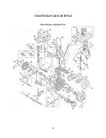
Page 29: ...CHAPTER 4 PART LISTINGS Diesel Engine Exploded View 29 ...
Page 32: ...Fig 4 1 Exploded view of engine block assembly 32 ...
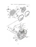
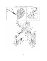
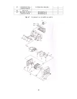
Page 35: ...Fig 4 2 Exploded view of cylinder head 35 ...
Page 38: ...Fig 4 3 Exploded view of Piston Crank Assembly 38 ...
Page 40: ...Fig 4 4 Exploded view of fuel tank parts 40 ...
Page 43: ...Fig 4 5 Lubrication and speed control system 43 ...
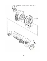
Page 46: ...Fig 4 6 Exploded view of cooling and recoil starting system 46 ...
Page 49: ...49 ...
Page 52: ...OWNER S MANUAL Air cooled diesel engine generator set DG4LE DG6LE 1 ...
Page 60: ...9 ...
Page 61: ...10 ...
Page 71: ...20 ...
Page 80: ...29 Figure 5 3 Exploded view of frame assembly ...

