background image


KS 86-1702503


1


KS 70-1702502


1


KS 78-1702602


1


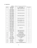
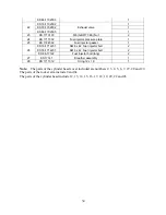
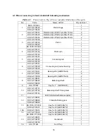
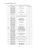
22


KS 86-1702605


Exhaust valve


1


23


KS 1710103


M6 (GB6177-86) Nut

2


24


KS 1717302


Fuel injector pressure plate

1


25


KS 1724502


Fuel injector gasket

1


KS 70-1712201


AM 6 x 42 Fuel injector bolt

2


KS 78-1712201


AM 6 x 42 Fuel injector bolt

2


26


KS 86-17122


Fuel injector bolt (long)

2


27


KS 17141


Breather assembly

1


28


KS 1711312


O ring 12 x 1.9

1


Note:  

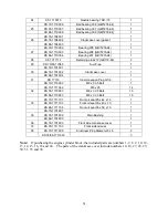
The parts of the cylinder head cover included are numbers 2, 3, 4, 5, 6, 7, 27, 28 and 29. 

The parts of the rocker arm include 9 and 9a. 
The parts of the cylinder head include 12, 13, 14, 15, 16, 17, 18, 19, 20, 22 and 26. 


34 

Summary of Contents for 170F

Page 1: ...OWNER S MANUAL AIR COOLED DIESEL ENGINE 170F FE FS FSE 178F FE FS FSE 186F FE FS FSE 1 ...

Page 2: ...nes are compact and lightweight They are easily maintained and portable making it convenient to move They are widely used as a source of mechanical power for industrial agricultural and machinery equipment Some applications include irrigation equipment diesel powered pressure sprayers grass cutting machines and soil sampling machines Other applications include vibration rammers shock rammers marin...

Page 3: ...ectric starter 21 2 3 3 Cold starting 21 2 4 Running and stopping the diesel engine 23 2 4 1 Running the diesel engine 23 2 4 2 Routine checks while engine is running 23 2 4 3 Stopping the engine 23 Chapter 3 Technical Maintenance of Diesel Engine 25 3 1 Daily checks and maintenance 25 3 2 Regularly checks and maintenance 25 3 3 Storing the engine for long periods of time 27 Chapter 4 Part Listing...

Page 4: ... or in a poorly ventilated area such as a tunnel or cave etc Exercise extreme care when operating the engine near people or animals Keep the exhaust pipe free of external objects REFUELING PRECAUTIONS Be sure to stop the engine before refueling Do not overfill the fuel tank If fuel is spilled wipe it away carefully and wait until the fuel has dried before starting the engine again When changing oi...

Page 5: ...dous materials PROTECTIVE COVER Always place the protective covers over the rotating parts If rotating parts such as the driving pulley belts and shafts are exposed serious injuries can be caused To prevent injury please equip all rotating parts with protective covers Be careful of hot parts The muffler and other engine parts can become very hot while the engine is running or after the engine has ...

Page 6: ...gine while it is in operation If the engine will be transported over a long distance drain all the fuel from the fuel tank to prevent fuel leakage PRE OPERATION CHECKS Carefully check fuel pipes and fuel joints for fuel leakage Leaked fuel creates a dangerous situation Verify that all the nuts and bolts of the engine are tights A loose nut or bolts may cause serious engine failure and could lead t...

Page 7: ...ntinuous 4 0 5 9 8 85 Output HP Maximum 4 5 6 6 9 85 Fuel tank capacity 66 9 1 45 US gallons Full 27 1 37 17 55 75 Lube oil Capacity oz Effective 8 45 13 51 20 27 Crankshaft direction Clockwise from flywheel end Cooling type Forced air cooled by flywheel fan Lubrication type Pressure splash Starting system Recoil manual start and or optional electric start Dry weight recoil lbs 60 73 106 Dry weigh...

Page 8: ...Output kw Maximum 3 36 4 92 7 3 Fuel tank capacity 2 5 3 4 5 5 Liters Full 8 1 10 1 65 Lube oil Capacity L Effective 25 40 60 Crankshaft direction Clockwise from flywheel end Cooling type Forced air cooled by flywheel fan Lubrication type Pressure splash Starting system Recoil manual start and or optional electric start Dry weight recoil kg 27 33 48 Dry weight elec kg 31 38 53 Dimensions LxWxH 332...

Page 9: ...ust be a tight stationary foundation for the diesel engine to avoid vibrations or movement when the engine is running For prolonged engine life consider using some type of motor mount 2 Make sure that the centering position of the output shaft is properly aligned 9 ...

Page 10: ...ary diameters of the various wheels is provided below The diameter of driving wheel belt wheel can be calculates as follows Diameter of engine driving wheel engine pulley Diameter of driven machine x speed of driven machine Diesel speed engine speed 5 Make sure that the belt has a correct tension to it Note If the belt is to tight the engine bearings will wear at a high rate leading to engine fail...

Page 11: ...alues shown in Fig 1 2 Fig 1 1 Allowed driving angles Fig 1 2 Allowed tilt angles Model Units amp hours 170F 18 24 178F 24 26 186F 1 2 3 Please contact our dealers about the electric circuits involved with this engine We recommend the use of accumulators rated at 20 hours shown in table 1 2 Table 1 2 36 45 11 ...

Page 12: ...1 2 Diesel Engine shaft specifications units mm 12 ...

Page 13: ...Sizes of PTO flanges Diesel Engine Power Curves 1 4 Names of Diesel Engine Parts 13 ...

Page 14: ... of fuel delivery and valve clearances Units Degrees Table 1 3 1 5 2 Initial angle of fuel delivery Units Degrees Table 1 4 1 5 3 Valve Clearances Table 1 5 1 6 Temperature ranges for exhaust and injection pressure specifications 14 ...

Page 15: ...1 7 Torque specifications for various engine nuts and bolts Table 1 7 Torque specifications in SI units Units N m 15 ...

Page 16: ...is running The engine should be placed in a simple ventilated place 3 Do not touch the muffler when the engine is running or just after it has stopped 4 The diesel engine should be operated at its rated power and rated speed If abnormal operating conditions are detected stop the engine immediately to check and fix the problem 5 A new engine must be properly broken in For the first 20 hours run the...

Page 17: ...engine Muffler The factory has replaced the engine fuel and engine oil once already To check the fuel pipeline make sure the fuel line is completely drained IF there is air in the pipeline drain it out To do this loosen the nut between the injection pump and fuel pipe then drain out the air until there are no bubbles left in fuel line Oil Lubricant Inlet Place the engine on level ground and fill t...

Page 18: ...ngine will shorten if it is overloaded during its break in period For the first 20 hours the engine must be started and stopped according to the test run method Avoid overloading the engine Change the engine oil regularly Below a table for the interval of oil changes will be provided 18 ...

Page 19: ...2 3 Starting the Diesel Engine 2 3 1 Recoil Starting Note When the engine is running do not pull the recoil handle otherwise the engine may be damaged 19 ...

Page 20: ...20 ...

Page 21: ... may be damaged Keep the key switch in the ON position 2 Battery a Always check the liquid level of the battery every month if the level is lower than the low limit mark refill the battery with distilled water till you reach the upper limit mark If the liquid level in the battery is to low the electric starter will not function to its best potential Always keep the level of the liquid in the batte...

Page 22: ...r cleaner for easy starting of the engine doing so may cause explosions from the intake gases Never take the oil plug unless you re planning on filling the oil If the plug is not in place rain dust and other impurities may be sucked into the engine causing serious damage to the engine parts 22 ...

Page 23: ...e not recommended for the engine as that will decrease engine life 3 Check to see the color of the exhaust gases to see if it is to white or to black 4 If any of these conditions are detected stop the engine immediately and contact your nearest dealer for repair information 2 4 3 Stopping the engine 1 First bring down the speed of the engine by using the speed governor Let it run for 3 minutes at ...

Page 24: ...and this means the piston is on the compression stroke where the intake and exhaust valves are closed and then let the handle recoil back into the engine This natural position will prevent rust from occurring when the engine is being stored for long periods of time Note Only perform step 5 when the engine is off Doing so otherwise will damage the engine 24 ...

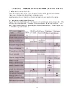
Page 25: ...ep the engine clean by cleaning up the dirt and other greasy deposits on the engine 3 2 Regularly checks and maintenance Regular checks and maintaining are very important for normal operation and engine life The following table indicates what is necessary to be performed at specific time intervals The marks signify that a special tool or technique is needed for maintenance Please contact your loca...

Page 26: ...26 ...

Page 27: ...ll incorrect air fuel mixture This will lead to poor performance of the diesel engine Always keep the air filter and air filter core clean 3 3 Storing the engine for long periods of time Please follow the instructions below if you plan on storing the engine for long periods of time 1 Run the engine for three minutes to burn out the excess fuel in the chamber 2 Quickly drain way the engine oil lubr...

Page 28: ...arter hold down the decompression lever and turn the start key switch to the start position Let the engine rotate for about two to three seconds Once again this pushes all the excess intake mixture out of the combustion chamber 6 Now pull the decompression lever up and pull on the recoil starter slowly until you feel resistance The resistance point occurs on the compression stroke where the intake...

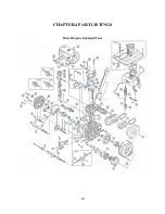
Page 29: ...CHAPTER 4 PART LISTINGS Diesel Engine Exploded View 29 ...

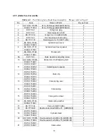
Page 30: ...6 1 KS 70 1700201 2 8 KS 78 1700202 Cylinder head bolts long 2 KS 86 1700203 2 KS 70 1700301 2 9 KS 78 1700302 Cylinder head bolts short 2 KS 86 1700303 2 KS 70 1700107 2 10 KS 78 1700103 Engine block 1 KS 86 1700110 1 KS 70 1711702 1 11 KS 78 1711702 Rear oil seal 30 x 45 x 8 1 KS 86 1711704 Rear oil seal 35 x 50 x 8 1 12 KS 17121 Oil drain plug 1 13 KS 17120 Oil drain plug gasket 1 14 KS 1711324...

Page 31: ... 1 31 KS 17133 Inner Hexagon Plug G1 8 1 KS 70 1710083 M8 x 33 5 Bolt 1 KS 70 1711062 M6 x 25 14 32 KS 78 1710083 M8 x 33 5 Bolt 15 KS 86 1710083 M8 x 33 5 Bolt 16 KS 70 1711701 Front oil seal 25 x 42 x 10 1 33 KS 78 1711703 Front oil seal 30x 45 x 10 1 KS 86 1711705 Front oil seal 35 x 50 x 10 1 KS 70 1701801 1 35 KS 78 1701802 Main Bushing 1 KS 86 1701803 1 36 KS 78 1701903 Front side crankcase ...

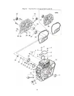
Page 32: ...Fig 4 1 Exploded view of engine block assembly 32 ...

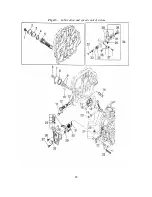
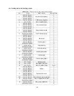
Page 33: ...clearance adjusting screw 2 KS 70 78 1710745 1 10 KS 86 1716901 Rocker arm shaft fastening bolt 1 KS 70 1705201 2 KS 78 1705202 Adjusting valve spacer 2 11 KS 86 1705203 2 KS 70 1702701 4 KS 78 1702702 4 12 KS 86 1702703 Valve clip 4 KS 70 1702801 2 KS 78 1702802 2 13 KS 86 1702803 Valve spring seat 2 KS 70 1702901 2 KS 78 1702902 2 14 KS 86 1702903 Valve spring 2 KS 70 1702003 2 KS 78 1702004 2 1...

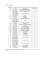
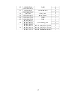
Page 34: ...0 1712201 AM 6 x 42 Fuel injector bolt 2 KS 78 1712201 AM 6 x 42 Fuel injector bolt 2 26 KS 86 17122 Fuel injector bolt long 2 27 KS 17141 Breather assembly 1 28 KS 1711312 O ring 12 x 1 9 1 Note The parts of the cylinder head cover included are numbers 2 3 4 5 6 7 27 28 and 29 The parts of the rocker arm include 9 and 9a The parts of the cylinder head include 12 13 14 15 16 17 18 19 20 22 and 26 ...

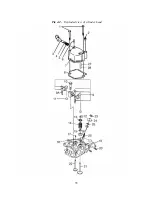
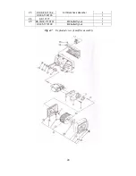
Page 35: ...Fig 4 2 Exploded view of cylinder head 35 ...

Page 36: ...Connecting rod 1 KS 70 1701501 1 KS 78 1701502 1 6 KS 86 1701503 Connecting rod journal bearing 1 KS 70 1710001 2 KS 78 1710001 Bearing 202 GB T276 94 2 7 KS 86 1710000 Bearing 203 GB T276 94 2 KS 70 1706501 1 KS 78 1706502 1 8 KS 86 1706503 Balancing Shaft 1 9 KS 1710507 Key 5 x 7 GB1096 79 2 KS 70 1707701 1 KS 78 1707702 1 10 KS 86 1707703 Balancing Shaft Timing Gear 1 11 Bolt included with dies...

Page 37: ...7 2 24 KS 86 1715701 Tappet 2 KS 70 86 1710514 Key 5 x 14 GB1096 79 1 25 KS 78 1710504 Key 4 x 12 GB1096 79 1 KS 70 1701001 1 KS 78 1701002 1 26 KS 86 1701000 Camshaft 1 26S KS 78 1701003 Front Side Camshaft 1 KS 70 1701101 1 KS 78 1701102 1 27 KS 86 1701103 Camshaft timing gear 1 28 KS 78 1700702 FS crankshaft 1 30 KS 78 1710545 Key 8 x 45 GB1096 79 camshaft key 1 31 KS 78 1704403 FS Flywheel 1 3...

Page 38: ...Fig 4 3 Exploded view of Piston Crank Assembly 38 ...

Page 39: ... M6 GB6177 86 Fuel drain gasket 1 13 KS 17152 Fuel drain plug 1 14 KS 17183 Lower fuel tank bracket 1 15 KS 1710714 M6 x 14 GB5787 86 Bolt 2 16 KS 1710106 M6 GB6177 86 Nut 2 17 KS 1710206 M6 GB97 1 85 Flat washer 1 18 KS 17150 Fuel tank cock assembly 1 19 KS 17154 Flat washer 1 20 KS 1719403 Fuel pipe clamp 2 21 KS 17189 Fuel pipe 1 22 KS 17148 Fuel filter gasket 1 KS 70 1704301 1 KS 78 1044302 1 ...

Page 40: ...Fig 4 4 Exploded view of fuel tank parts 40 ...

Page 41: ... GB5789 86 1 12 KS 78 86 1702103 Oil filter cleaning element 1 KS 70 1711314 Sealing ring 20 x 2 5 1 13 KS 78 86 1711316 Sealing ring 20 x 2 65 1 14 KS 78 86 17080 Oil Guide 1 KS 70 1702301 1 KS 78 1702302 1 15 KS 86 1702302 Oil pump driving gear 1 16 KS 17132 Fly block pin 1 17 KS 17131 Fly block 2 18 KS 17234 Governor fork tappet 2 19 KS 17125 Lever shaft gasket 1 20 KS 1710009 Bearing 7941 8 GB...

Page 42: ... 32 KS 1710645 M6 x 45 GB6172 86 Bolt 1 33 KS 1710111 M10 x 1 25 Nut 1 34 KS 1706701 FG Lever 1 35 KS 1706901 FG governor spring 1 36 KS 1710714 M6 x 14 GB5789 86 Bolt 1 37 KS 1710106 M6 GB39 88 Nut 1 38 KS 1716801 Washer 2 39 KS 1730720 Shaft Handle 1 42 ...

Page 43: ...Fig 4 5 Lubrication and speed control system 43 ...

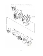
Page 44: ... 1 KS 70 1704003 2 7 KS 78 86 1704005 Starting claw 2 KS 70 17218 1 8 KS 78 86 1721801 Helical spring 1 KS 70 17219 1 9 KS 78 86 1721901 Torsional spring 1 KS 70 1704004 1 10 KS 78 86 1704006 Starting claw plate 1 KS 70 17039 1 11 KS 78 86 1703902 Friction plate 1 KS 70 1703903 1 12 KS 78 86 1703803 Friction plate gasket 1 13 KS 1710306 Spring washer 1 14 KS 1710106 M6 GB6170 86 Nut 1 15 KS 171071...

Page 45: ...4 Shock pads 1 23 KS 78 86 17127 Shock isolator 1 24 KS 78 86 17129 Collar 1 25 KS 78 86 17128 Pad 1 KS 70 1700401 1 KS 78 1700402 1 26 KS 86 1700403 Wind leading plate 1 KS 70 1710712 M6 x 12 shaped piece Bolt 1 KS 78 1710718 M6 x 18 shaped piece Bolt 1 27 KS 86 1710614 M6 x 22 shaped piece Bolt 1 45 ...

Page 46: ...Fig 4 6 Exploded view of cooling and recoil starting system 46 ...

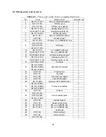
Page 47: ...sket 1 KS 70 1705401 1 KS 78 1705402 1 10 KS 86 1705403 Muffler assembly 1 11 KS 1710208 Flat washer Dia 8 2 12 KS 1710308 Spring washer Dia 8 2 13 KS 1710108 M8 GB6170 86 Nut 1 KS 70 1710714 M6 x 14 GB5789 86 Bolt 2 14 KS 78 86 1710757 M8 x 14 GB5789 86 Bolt 2 KS 70 1705501 1 KS 78 1705502 1 15 KS 86 1705503 Muffler screen cover 1 16 KS 1710708 M6 x 14 GB5789 86 Bolt 1 KS 70 78 1705404 1 17 KS 86...

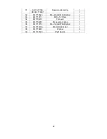
Page 48: ...KS 70 78 17182 1 23 Air filter shock absorber KS 86 1720106 1 24 KS 17177 1 KS 70 78 1710107 M6 butterfly nut 1 25 KS 85 1710109 1 M8 butterfly nut Fig 4 7 Exploded view of muffler assembly 48 ...

Page 49: ...49 ...

Page 50: ...et of the cylinder head may be leaking and the pressure of compression is not held Fix each component that is necessary to achieve correct compression and a correct angle of spray Fuel delivery is not constant Fuel level in fuel tank may be to low Fill the fuel tank until it is full Or the fuel pipe or fuel filter may be clogged fix this by replacing them Low compression Replace head gasket or tig...

Page 51: ...fuel system Clean out the system and put new fuel in Needle valve of nozzle adhered Clean or grind the nozzle if necessary replace the nozzle Air filter is clogged Clean the air filter The load suddenly increases Decrease the load 5 4 Engine exhaust very black Possible cause Remedy Overloaded engine Decrease the load If driven machine is not properly fitted with proper engine change the engine Bad...

Page 52: ...OWNER S MANUAL Air cooled diesel engine generator set DG4LE DG6LE 1 ...

Page 53: ...ect fuel injection system Recoil starter or an optional electric starter Large fuel tank Automatic voltage stabilizer NFB circuit protector AC and DC outputs Low oil pressure sensor The ETQ air cooled diesel generators are widely used when electrical power is scarce Our generators provide a portable mobile solution in supplying power for field operations during project construction Some other know...

Page 54: ...hecking the operation of the diesel engine 16 2 4 Starting the generator set 16 2 5 Procedures for starting the generator set 19 2 6 Proper operation of the generator set 21 2 7 Loading 21 2 8 Stopping the generator 23 Chapter 3 Maintenance 24 3 1 Maintenance schedules 24 3 2 Storing for long periods of time 26 Chapter 4 Troubleshooting 27 4 1 Overhauling and troubleshooting procedures 27 4 2 Ques...

Page 55: ...4 2 Overall view of DG4LE series 4 Overall view of DG6LE 3P series 1 Overall view of DG3LE series 3 Overall view of DG6LE series ...

Page 56: ...lf excitation voltage Generator Insulation B Engine model ETQ170FG ETQ178FG ETQ186FG ETQ186FG Type Single cylinder vertical 4 stroke air cooled direct injection Continuous kw 2 98 4 40 6 6 6 6 Output Maximum kw 3 36 4 9 7 34 7 34 Bore x Stroke mm 70 x 55 78 x 62 86 x 70 86 x 70 Displacement cc 219 306 418 418 Cooling system Forced air cooling by flywheel fan Lubricating system Pressure splash dupl...

Page 57: ...ne model ETQ170FG ETQ178FG ETQ186FG ETQ186FG Type Single cylinder vertical 4 stroke air cooled direct injection Continuous HP 4 0 5 9 8 85 8 85 Outp ut Maximum HP 4 5 6 6 9 85 9 85 Bore x Stroke in 2 76 x 2 17 3 01 x 2 44 3 39 x 2 76 3 39 x 2 76 Displacement cu in 13 36 18 67 25 51 25 51 Cooling system Forced air cooling by flywheel fan Lubricating system Pressure splash duplex type lubrication Lu...

Page 58: ...tor will output the specified power in the table listed below Table 1 Height above sea level ft Ambient temperature o F RH 0 60 20 o C 60 3280 8 1000 m 41 104 5 40 o C 90 1 3 General dimensions and overview of the generators 1 3 1 General dimensions of the LN series generators ...

Page 59: ...8 1 4 Electric wiring diagrams for various models of generators Wiring diagrams for the LE models ...

Page 60: ...9 ...

Page 61: ...10 ...

Page 62: ...and may lead to failure of the engine 2 1 2 Prevention from inhaling exhaust gases Never inhale exhaust gases emitted by the engine The exhaust gases contain toxic carbon monoxide Never operate your generator in places with poor ventilation In order to operate this machinery indoors a suitable ventilation system for the building is required to draw the poisonous exhaust gases out 2 1 3 Prevention ...

Page 63: ...with all the switches and functions of the generator before using this machine While operating the generator wear safe shoes and suitable clothes during operation Always keep children and animals away from the generator 2 1 6 Battery The electrolytic liquid of the battery also known as battery acid contains sulfuric acid In order to protect your eyes skin and clothing wear protective gear when wor...

Page 64: ...ld be filtered clean Never let dust and water mix with fuel in the fuel tank Otherwise it will clog the fuel lines and oil nozzles It may also damage your pressure pump Note It is dangerous to overfill the fuel tank Never exceed the red piston in the filter a After purchasing fuel put it into a drum and let it sit for 3 4 days b 3 4 days later insert half of the fuel sucker into the drum water and...

Page 65: ...rly the piston and cylinder will wear easily or seize up Also the life of the other parts in your engine such as bearings and other rotating parts will shorten considerably Although there is an alarm system to check for low oil pressure it is always a good idea to check the amount of oil inside the engine If the oil level is low fill it before starting the engine A good time to drain the oil from ...

Page 66: ...switch in the On switch is very dangerous Air filter cover The generator should be grounded in order to prevent electric shock Use dry compressed air with pressure about 1 96 x 105 Pa to blow the dust out in the electric control cabinet and at the surface of the generator Check to see how clean the surface of the sliding ring is Check the pressure of the carbon brush Also check whether the positio...

Page 67: ...e engine the engine oil can slow the engine down considerably 2 3 2 How to open the case door cover 1 Open the case door turn the handle counterclockwise and open the door Do these checks daily 2 Loosen the outer cover bolt of the air filter and outer cover of the oil nozzle and then check the air filter 3 Check the outer cover of the oil nozzle Loosen the butterfly nut and open the outer cover 2 ...

Page 68: ...edy this pull the rubber plug out from the rocker of the diesel engine and fill 2 ml of engine oil Before starting put the rubber plug back in place If you don t put the rubber plug back in place rain dust and other dirt can enter into the diesel engine It will cause the parts inside the diesel engine to wear quickly and lead to engine failure 2 4 2 Electric starting The procedures for preparing t...

Page 69: ...maintain your battery check the height of the battery acid once a month If the level of the liquid drops too low fill it with distilled water until it reaches the high mark If there is not enough battery acid then the diesel engine cannot be started It is important to keep the liquid level between the high and low limits If the level in the battery is to high the liquid may flow out and end up on ...

Page 70: ...19 2 5 Procedures for starting the generator set This procedure applies to the L series recoil starting style models ...

Page 71: ...20 ...

Page 72: ...hether it is too black or too white If any of these conditions exist stop the engine and find the cause of the problem If no problems are found please contact your local dealer or our nearest company branch 2 7 Loading 2 7 1 Load conditions Exert loads in accordance with the specified parameters 2 7 2 Output of electricity 1 Raise the revolutions per minute turn the speed handle to the max setting...

Page 73: ...art more than two devices simultaneously Each device should be started one by one to prevent overloading the generator The generator should be running at 3600 revolutions per minute in order to achieve the 60 Hz frequency The speed of the engine can be adjusted from the speed governor 2 7 3 Charging the battery 1 For the electric starter on the generator welder the 12V battery is automatically cha...

Page 74: ...y to the Off position 5 Put the fuel handle to the S position 6 Finally pull slowly on the recoil handle until you feel resistance this is when the piston is on the compression stroke where the intake and exhaust valves are closed What this does is prevent the engine from rusting when not in use Speed handle Note 1 If the speed handle is in the Stop position and the engine is still running turn th...

Page 75: ...ator control cabinet and frame For overhauling procedures please refer to the instruction manual of the relative subassembly If you need these manuals please call our company and we will send you one Before starting the maintenance make sure the diesel engine is off Please refer to the Table 3 1 for the proper maintenance schedule Table 3 1 Maintenance schedule for diesel welder generator set ...

Page 76: ... tank b Loosen the small screws on the fuel switch and remove the fuel filter form the port Use diesel fuel to clean the fuel filter Also remove the fuel injector and clean the carbon deposit around it The recommended time period for this is 3 months or 100 hours Dipstick High pressure fuel pipe bolt Oil drain bolt 3 1 4 Cylinder head bolt tensions The cylinder head bolts should be tightened to sp...

Page 77: ...rs press the decompression handle down and pull the recoil handle 2 or 3 times This pushes the intake out Do not start the engine 5 For electric started generator welders press the decompression handle down and crank the engine for 2 3 seconds To do this put the starter switch in the Start position Do not start the diesel engine 6 Finally pull the recoil starter until you feel resistance this is w...

Page 78: ...any questions please feel free to contact your local dealer or with our company directly Below is a list of some information you should have ready before contacting your local dealer or us 1 Model of diesel engine generator and engine model number 2 State of residency 3 Number of hours of operating equipment along with the problem that occurred 4 A detailed condition and time when the problem occu...

Page 79: ...el generator 1 ETQ4LE3 ETQ6LE3 4 Bolt 2 ETQ4LE4 ETQ6LE4 5 Voltage Regulator 1 ETQ4LE5 ETQ6LE5 6 Battery Cable red 1 ETQ4LE6 ETQ6LE6 7 Battery Cable black 1 ETQ4LE7 ETQ6LE7 8 Battery 1 ETQ4LE8 ETQ6LE8 9 Oil level sensor 1 ETQ4LE9 ETQ6LE9 10 Output panel assembly 1 ETQ4LE10 ETQ6LE10 11 Throttle cable 2 ETQ4LE11 ETQ6LE11 12 Connector assembly 1 ETQ4LE12 ETQ6LE12 13 Capacitor 1 ETQ4LE13 ETQ6LE13 14 Bo...

Page 80: ...29 Figure 5 3 Exploded view of frame assembly ...

Page 81: ...38 23 Spring washer 6 1 ETQ4LE39 ETQ6LE39 24 M6 x 35 Bolt 1 ETQ4LE40 ETQ6LE40 25 M10 Nut 2 ETQ4LE41 ETQ6LE41 26 Spring washer 10 2 ETQ4LE42 ETQ6LE42 27 Flat washer 10 2 ETQ4LE43 ETQ6LE43 28 M10 x 20 2 ETQ4LE44 ETQ6LE44 29 Bracket 1 ETQ4LE45 ETQ6LE45 30 M10 Nut 4 ETQ4LE46 ETQ6LE46 31 Spring washer 10 4 ETQ4LE47 ETQ6LE47 32 Flat washer 10 4 ETQ4LE48 ETQ6LE48 33 Rubber mounts 4 ETQ4LE49 ETQ6LE49 34 F...

Page 82: ...LE77 10 3 prong Socket 2 ETQ4LE78 ETQ6LE78 11 Bolt 6 ETQ4LE79 ETQ6LE79 12 Electric panel bolt 6 ETQ4LE80 ETQ6LE80 13 Electric Panel 1 ETQ4LE81 ETQ6LE81 14 Starter switch 1 ETQ4LE82 ETQ6LE82 15 Large nut 6 ETQ4LE83 ETQ6LE83 16 Oil alert lamp 1 ETQ4LE84 ETQ6LE84 17 Hour meter 1 ETQ4LE85 ETQ6LE85 18 Hour meter bolts 2 ETQ4LE86 ETQ6LE86 19 DC Fuse 1 ETQ4LE87 ETQ6LE87 20 Voltmeter 1 ETQ4LE88 ETQ6LE88 2...

Page 83: ...LE98 4 Fan Blade 1 ETQ4LE99 ETQ6LE99 5 Bearing 1 ETQ4LE100 ETQ6LE100 6 Rotor Unit 1 ETQ4LE101 ETQ6LE101 7 Center bolt 1 ETQ4LE102 ETQ6LE102 8 Motor cover 1 ETQ4LE103 ETQ6LE103 9 Stator 1 ETQ4LE104 ETQ6LE104 10 Long bolt 4 ETQ4LE105 ETQ6LE105 11 Capacitor 1 ETQ4LE106 ETQ6LE106 12 Wiring Seat 1 ETQ4LE107 ETQ6LE107 13 M5 x 15 Bolt 6 ETQ4LE108 ETQ6LE108 14 Stator Unit 1 ETQ4LE109 ETQ6LE109 15 Dust Cov...

Page 84: ... Shock absorbing gasket 4 ETQ4LE119 ETQ6LE119 10 Fuel tank 1 ETQ4LE120 ETQ6LE120 11 M6 Nut 4 ETQ4LE121 ETQ6LE121 12 O ring seal 1 ETQ4LE122 ETQ6LE122 13 Fuel tank filter 1 ETQ4LE123 ETQ6LE123 14 O ring gasket 1 ETQ4LE124 ETQ6LE124 15 Fuel filter cover 1 ETQ4LE125 ETQ6LE125 16 Cover 1 ETQ4LE126 ETQ6LE126 17 Wing nut 1 ETQ4LE127 ETQ6LE127 18 Fuel line 2 ETQ4LE128 ETQ6LE128 19 Fuel inlet pipe 1 ETQ4L...

Page 85: ...U S A AND CANADA ENGINES CONSUMER USE COMMERCIAL USA CONSUMER USE COMMERCIAL USE DIESEL GENERATOR 1 year or 1000 hours 1 year or 1000 hours 1 year or 1000 hours 1 year or 1000 hours About Your Product Warranty Eastern Tools Equipment Inc welcomes warranty repair and apologizes to you for being inconvenienced Any Authorized Service Dealer may perform warranty repairs Most warranty repairs are handl...

Page 86: ...ives Some applications such as tillers pumps and rotary movers are very often used in dusty or dirty conditions which can cause what appears to be premature wear Such wear when caused by dirt dust spark pug cleaning grit or other abrasive material that has entered the engine because of improper maintenance is is not covered by warranty ...

Page 87: ... Model Number Address of user Occupation Place of purchase Packaging conditions Operating conditions Parts Conditions Malfunction problem Opinions or suggestions Note Please mail the above card to Eastern Tools Equipment Inc 12220 Rivera Rd Suite B Whittier CA 90606 ...

Page 88: ...diesel welder and generator set 1 2 Kit 1 3 Plastic cover 1 4 Plug and power supply 1 2 Attached technical documents Order No Name Qty Remarks 1 Air cooled diesel welder and generator manual 1 2 Diesel engine instruction manual 1 3 Diesel engine parts listing 1 4 Certificate of Quality 1 5 Packing List 1 ...

Page 89: ...38 EASTERN TOOLS EQUIPMENT INC TEL 1 626 960 6299 FAX 1 626 960 6244 WEB SITE http easterntools com ...

Reviews: