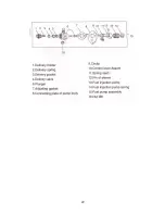
4-3 Piston connecting rod and crankshaft balancing mechanism
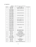
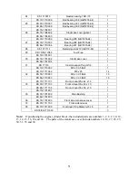
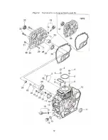
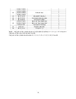
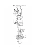
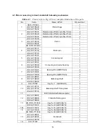
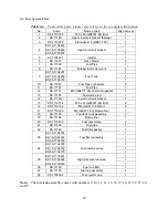
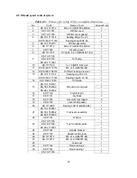
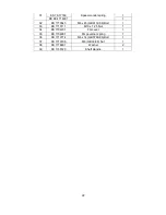
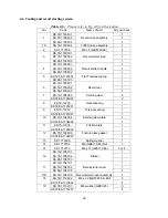
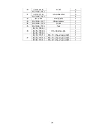
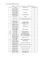
Table 4-3. Please refer to Fig 4-3 for a complete illustration of the parts.
No.
Code
Name of Part
Qty each set
KS70-1701403
1
KS 78-1701402
1
1
KS 86-1701404
Piston Rings
1
KS 70-1701601
Retainer clip of Piston pin Dia. 19mm
2
KS 78-1701602
Retainer clip of Piston pin Dia. 21mm
2
2
KS 86-1701603
Retainer clip of Piston pin Dia. 23mm
2
KS 70-1701200
1
KS 78-1701202
1
KS 86-1701204
1
3
KS 78FS-1701203
Piston
1
KS 70-1701701
1
KS 78-1701702
1
4
KS 86-1701703
Piston pin
1
KS 70-1701301
1
KS 78-1701302
1
5
KS 86-1701303
Connecting rod
1
KS 70-1701501
1
KS 78-1701502
1
6
KS 86-1701503
Connecting rod journal bearing
1
KS 70-1710001
2
KS 78-1710001
Bearing 202 (GB/T276-94)
2
7
KS 86-1710000
Bearing 203 (GB/T276-94)
2
KS 70-1706501
1
KS 78-1706502
1
8
KS 86-1706503
Balancing Shaft
1
9
KS 1710507
Key 5 x 7 (GB1096-79)
2
KS 70-1707701
1
KS 78-1707702
1
10
KS 86-1707703
Balancing Shaft Timing Gear
1
11
Bolt (included with diesel engine)
1
KS 70-1700801
1
KS 78-1700802
1
12
KS 86-1700803
Crankshaft timing gear
1
KS 70/78-1710512
Key 5 x 12 (GB1096-79)
2
13
KS 86-1710512
Key 5 x 12 (GB1096-79)
1
13A
KS 86-1710514
Key 5 x 14 (GB1096-79)
1
KS 70-1710530
Key 5 x 30 (GB1096-79)
1
14
KS 78/86-1710563
Key 6 x 63 (GB1096-79)
1
KS 70-1700601
1
KS 78-1700701
1
15
KS 86-1700708
Crankshaft
1
16
KS 1711601
6 x 8 Plug
1
36
Summary of Contents for 170F
Page 1: ...OWNER S MANUAL AIR COOLED DIESEL ENGINE 170F FE FS FSE 178F FE FS FSE 186F FE FS FSE 1 ...
Page 12: ...1 2 Diesel Engine shaft specifications units mm 12 ...
Page 13: ...Sizes of PTO flanges Diesel Engine Power Curves 1 4 Names of Diesel Engine Parts 13 ...
Page 20: ...20 ...
Page 26: ...26 ...
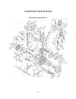
Page 29: ...CHAPTER 4 PART LISTINGS Diesel Engine Exploded View 29 ...
Page 32: ...Fig 4 1 Exploded view of engine block assembly 32 ...
Page 35: ...Fig 4 2 Exploded view of cylinder head 35 ...
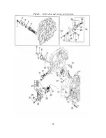
Page 38: ...Fig 4 3 Exploded view of Piston Crank Assembly 38 ...
Page 40: ...Fig 4 4 Exploded view of fuel tank parts 40 ...
Page 43: ...Fig 4 5 Lubrication and speed control system 43 ...
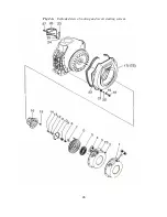
Page 46: ...Fig 4 6 Exploded view of cooling and recoil starting system 46 ...
Page 49: ...49 ...
Page 52: ...OWNER S MANUAL Air cooled diesel engine generator set DG4LE DG6LE 1 ...
Page 60: ...9 ...
Page 61: ...10 ...
Page 71: ...20 ...
Page 80: ...29 Figure 5 3 Exploded view of frame assembly ...

