15
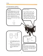
2-2.3 Checking the air filter
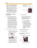
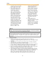
(1) Loosen the butterfly nut, take the
cover of the air filter off and take
the air filter element out.
Do not use detergent to wash the air
filter element. When the
performance of the engine decreases
or when the color of the exhaust
gases is bad, exchange the filter
element. Never start the engine
without the air filter as foreign
objects may enter the intake and
damage the engine.
(2) After replacing the air filter
element, replace the cover and
tighten the butterfly nut firmly.
2-2.4 Checking the generator welder
(Note: Only certain welder generator sets
have an electric fan incorporated on them.)
Butterfly nut
Before starting the generator, make
sure the air switch is in the “Off”
position. Starting the generator with
the switch in the “On” switch is very
dangerous.
Air filter cover
The generator should be grounded in
order to prevent electric shock.
Use dry compressed air (with
pressure about 1.96 x 10⁵ Pa) to
blow the dust out in the electric
control cabinet and at the surface of
the generator. Check to see how
clean the surface of the sliding ring
is. Check the pressure of the carbon
brush. Also, check whether the
position of the carbon brush at the
slide rig is correct and the fixture is
reliable with a good contact.
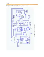
According to the electric wiring
diagram, check to see whether the
connecting wire is correct and the
connected place is firm.
Use a 500 M
Ω
meter to measure the
insulation resistance of the electrical
part. The resistance should be no
less than 5M
Ω
. When measuring
devices, make sure the AVR is
turned off. Otherwise, it will burn
the AVR. (For the low noise set, the
inspection may not be performed).
2-2.5 The fuel and oil in a new
engine is drained before sold.
Summary of Contents for 170F
Page 1: ...OWNER S MANUAL AIR COOLED DIESEL ENGINE 170F FE FS FSE 178F FE FS FSE 186F FE FS FSE 1 ...
Page 12: ...1 2 Diesel Engine shaft specifications units mm 12 ...
Page 13: ...Sizes of PTO flanges Diesel Engine Power Curves 1 4 Names of Diesel Engine Parts 13 ...
Page 20: ...20 ...
Page 26: ...26 ...
Page 29: ...CHAPTER 4 PART LISTINGS Diesel Engine Exploded View 29 ...
Page 32: ...Fig 4 1 Exploded view of engine block assembly 32 ...
Page 35: ...Fig 4 2 Exploded view of cylinder head 35 ...
Page 38: ...Fig 4 3 Exploded view of Piston Crank Assembly 38 ...
Page 40: ...Fig 4 4 Exploded view of fuel tank parts 40 ...
Page 43: ...Fig 4 5 Lubrication and speed control system 43 ...
Page 46: ...Fig 4 6 Exploded view of cooling and recoil starting system 46 ...
Page 49: ...49 ...
Page 52: ...OWNER S MANUAL Air cooled diesel engine generator set DG4LE DG6LE 1 ...
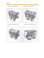
Page 60: ...9 ...
Page 61: ...10 ...
Page 71: ...20 ...
Page 80: ...29 Figure 5 3 Exploded view of frame assembly ...

