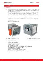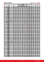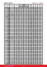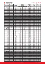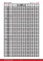
Kuvamateriaali on havainnollistava
Pidätämme oikeuden muutoksiin
RDT-07-0121
3
®
NORD
fire
|
FDMB
1.3 Working conditions
Right damper function is secured under the following conditions:
a) Maximum air circulation speed: 12 m/s
Maximum pressure difference: 1200 Pa
b) The air circulation in the whole damper section must be secured as steady on whole
surface.
Operation of the dampers does not depend on the direction of air circulation. The dampers can
be located in an arbitrary position.
Dampers are suitable for systems without abrasive, chemical and adhesive particles.
Dampers are designed for macroclimatic areas with mild climate according to EN 60 721-3-3.
Temperature in the place of installation is permitted to range from -30°C to +50°C.
2. Design
2.1 Design with mechanical control
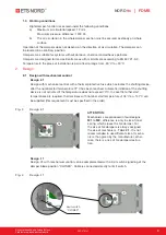
Design .01
Design with mechanical control with a thermal protective fuse which actuates the shutting device,
after the nominal start temperature 72°C has been reached. Automatic initiation of the shutting
device is not activated if the temperature does not exceed 70°C. In case that other start
temperatures are required, thermal fuses with nominal start tempe104°C or +147°C can
be supplied (this requirement must be specified in the order).
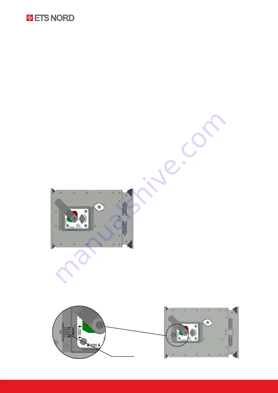
Fig. 3 Design .01
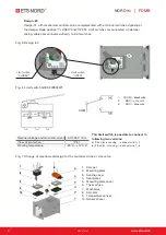
Design .11
Design .01 with mechanical control can be complemented with a limit switch signalling of the
damper blade position "CLOSED". Cable is connected directly to limit switch.
Fig. 4 Design .11
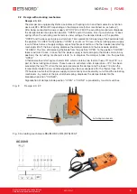
ATTENTION:
Mechanisms are produced in four designs
M1
to
M2
, difference is only in size of inner
spring, which closes the fire damper. For
the size of fire dampers is always assigned
the size of mechanism -
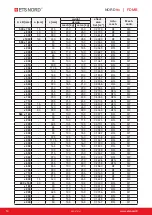
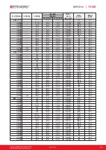
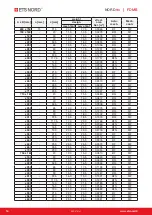
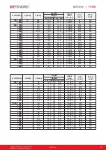
Tab 4.2.1.
It is not
recommended to use different size of mecha-
nism, than given by the manufacturer, other-
wise, there is a risk of fire damper destruc-
tion.
Limit switch
“CLOSED”


