2
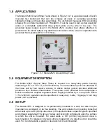
The hole pattern required is shown in Figure 3.0-1. It is recommended that the holes in
the base unit be used to locate the actual location of the holes.
To gain access to the mounting holes remove the front cover by unscrewing the four
captive screws. Carefully lift the cover and if necessary, disconnect the ribbon cable
from the selector switch PC Board.
CAUTION:
Disconnect the power cord whenever the front cover is removed.
115 or 240 VAC INSIDE.
Locate the mounting holes on the wall using the base as a template and then mount the
Model 253A using the appropriate screws.
Reconnect the ribbon cables. The connector is polarized. It can only fit into the mating
connector one way. The notch on the connector locks into a groove on the plastic
overhang of the PCB connector as shown in Figure 3.0-2.
3.55”
90mm
4.33”
110mm
Figure 3.0-1: Location of mounting holes
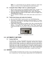
Figure 3.0-2: Interconnect cables


