background image


Model 5506 Mid-Size Chamber 

 Operating Manual 

D01332 Revision B  -  2021-03-16  -  Page 

3

 of 

20


I. Important Safety Information 

SAFETY INSTRUCTIONS 

The equipment described in this Manual is designed and manufactured to operate within defined 
design limits. Any misuse may result in injury, electric shock, or damage to the equipment. For safe 
operation, the following rules should be observed for installation, use, and maintenance.

 Read the 

following safety instructions before operating the instrument. 


POWER 

POWER CORD: Use only the power cord specified for this equipment and certified for the country of use. If the 
power (mains) plug is replaced, follow the wiring connections specified for the country of use. When installing 
or removing the power plug, 

hold the plug, not the cord. 

GROUNDING: The power cord provided is equipped with a

 3-prong grounded plug (a plug with a third 

grounding pin). 

This is both a safety feature to avoid electrical shock and a requirement for correct equipment 

operation. If the outlet to be used does not accommodate the 3-prong plug, either change the outlet or use a 
grounding adapter. 

FUSES:


Replace fuses only with those having the required current rating, voltage and specified type such as 

normal blow, time delay, etc. 

DO NOT

 use makeshift fuses or short the fuse holder. This could cause a shock 

or fire hazard or severely damage the instrument. 

OPERATION 


CAUTION


DO NOT OPERATE WITH COVERS OR PANELS REMOVED

. Voltages inside the equipment consist of line 

(mains) that can be anywhere from 100-240VAC.


DO NOT OPERATE WITH SUSPECTED EQUIPMENT FAILURES. 

If any odor or smoke becomes apparent, 

turn off the equipment and unplug it immediately. Failure to do so may result in electrical shock, fire or 
permanent damage to the equipment. Contact the factory for further instructions.  

DO NOT OPERATE IN AN EXPLOSIVE ATMOSPHERE: 

Operating the equipment in the presence of 

flammable gases or fumes 

constitutes a definite safety hazard

. For equipment designed to operate in such 

environments the proper safety devices must be used such as dry air or inert gas purge, intrinsic safe barriers 
and/or explosion-proof enclosures. 

DO NOT IMPEDE THE CHAMBER FROM VENTING EXCESS PRESSURE.

  Humidification and 

dehumidification systems may be open loop systems that pump external air into the chamber.  If the chamber 
is not allowed to vent, pressure could build up and cause serious damage to the chamber. 

USE DISTILLED OR DEIONIZED WATER SOURCE FOR HUMIDIFICATION.

  Build-up of contaminates on 

the humidifier transducer will cause stress to the transducer and electronics and resulting in premature failure 
and invalidate the warranty.  

DO NOT USE IN ANY MANNER NOT SPECIFIED OR APPROVED BY THE MANUFACTURER:


Unapproved use may result in damage to the equipment or present an electrical shock or fire hazard. 


Summary of Contents for 5506

Page 1: ...Electro Tech Systems 700 West Park Avenue Perkasie Pennsylvania 18944 D01332 Revision B Mid Size Environmental Chamber ETS Model 5506 Operating Manual...

Page 2: ...3 V Functionality 14 VI System Performance 16 VII Maintenance and Calibration 18 VIII Warranty 20 Revision History Revision A Released 2020 12 30 Reformatted Revision B Released 2021 03 02 Improved ph...

Page 3: ...d cause a shock or fire hazard or severely damage the instrument OPERATION CAUTION DO NOT OPERATE WITH COVERS OR PANELS REMOVED Voltages inside the equipment consist of line mains that can be anywhere...

Page 4: ...t and its power supply are mounted to the rear panel of the chamber A power cord for Cooling is attached Electric Heater Panel Model 5474 Resistive heater panel mounted in the rear of the chamber A re...

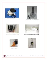
Page 5: ...hamber Operating Manual D01332 Revision B 2021 03 16 Page 5 of 20 Model 5482 Humidifier Model 5461 Desiccant Dehumidifier Model 5473 Thermoelectric Cooler Model 5478 Regenerating Dehumidifier Ports Gl...

Page 6: ...d of the chamber wall or gripping around the outside of the chamber Unpack the Control Unit and inspect for visible damage If no damage is observed then proceed to the next step Step 2 Set the chamber...

Page 7: ...Step 2 Controller 5000 series Place the controller in a convenient location and switch all front panel switches to the OFF 0 position Turn controller around to reveal the connections Switch the POWER...

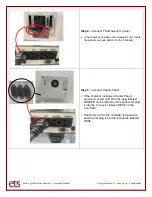
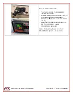
Page 8: ...nit locate the power cord and attach it to the Controller Step 5 Connect Heater Panel If the chamber includes a Heater Panel connect a power cord from the plug labeled HEATER on the left side of the p...

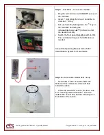
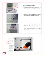
Page 9: ...sition the tank above the base unit and be sure the base unit is on a level surface Connect the water feeding tube from the 5 gallon tank to the humidifier as shown inserting tubing firmly into the co...

Page 10: ...crease decrease buttons to enter the desired humidity Switch the front panel Humidify switch to ON The controller will request humidification as needed Consult the Operating Manual for the 5482 Humidi...

Page 11: ...r Output fitting on the base unit to the IN 90 fitting on the column Cut tubing to length and connect from the Chamber Air Out fitting to the Model 5461 Air Input fitting Cut tubing to length and conn...

Page 12: ...HUMIDIFY socket of the controller Set a set point by holding down the key on the controller and using the increase decrease buttons to enter the desired humidity Switch the front panel Dehumidify swit...

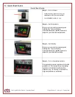
Page 13: ...set point by pressing and holding the key and using increase decrease buttons to adjust to your desired temperature Step 4 Set Humidity Enter your set point by pressing and holding the key and using...

Page 14: ...to the 0 is Off 3 TEMP INCR Switch Allows the user to manually disable the Temperature Heating System Pushing this switch to the 0 is Off 4 TEMP DECR Switch Allows the user to manually disable the Tem...

Page 15: ...ing AC power here 13 SENSOR Socket Attach the Model 556 Temperature and RH Sensor here 14 COOL Socket TEMP DECREASE Provides power to cooling system when needed 15 HEAT Socket TEMP INCREASE Provides p...

Page 16: ...nal 2 x 8 replaceable hands Iris Ports Optional 2 x 8 CONNECTIONS 1 1 2 Cable pass through 1 1 4 Quick disconnect 2 3 4 compression fitting 1 1 hose barb 1 Circulation fan Optional AC operation 32 cfm...

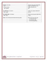
Page 17: ...tribution Fan Electrical Outlet Duplex outlet with cover Temp Highest 50 C Humidification if included Ultrasonic Humidifier Model 5482 RH highest 95 RH Dehumidification if included Desiccant drying sy...

Page 18: ...r replaceable Please contact ETS for assistance with repair replacement To maximize the life of the transducer utilize an appropriate water supply deionized water or distilled water and perform regula...

Page 19: ...out contaminates in the basin through the drain valve for 2 minutes Step 5 Return the System to operation Turn the drain valve to the OFF position tap turned to 90 from the valve body Review the Setu...

Page 20: ...ective workmanship or material Seller expressly disclaims all other warranties express and or implied including but not limited to those of merchantability and fitness for a particular purpose In no e...

Reviews: