Manufacturer
Distributor
13
5.4
Installation Sequence
1.
Drill the centre opening (select opening placement as shown in Fig. 3) for mounting the sensor, using a bi-
metal hole saw with a diameter of 35 mm. Insert the sensor in the opening and mark the spots for fastener
holes. A diagram of fastener hole placement is shown in Fig. 10.
Figure 10. Fastener Hole Placement
IMPORTANT NOTE:
In order to prevent an explosion of fuel fumes, a diesel tank MUST BE filled up to the
maximum prior to the drilling of any openings! The fuel tank of a petrol engine MUST BE either filled with
water or removed and the remaining petrol evaporated!
2.
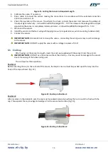
Cut the sensor to required length
–
see Fig. 11. Use a hacksaw to cut the aluminium tubes to tank height,
allowing for at least a 20mm gap between sensor end and tank floor for water/impurity accumulations.
Carefully remove any aluminium chips that stick between the tubes. Deburr the tube ends.
3.
Plug the end cap supplied with the sensor into the cut end (see section 5.5 for information on the cap).
IMPORTANT NOTE:
DO NOT use the sensor without the end cap
–
this may result in damage to the sensor
due to loosening of the tubes during use!
Summary of Contents for ETS.A
Page 1: ...Fuel Level Sensor ETS A Operating Manual...
Page 9: ...Manufacturer www ets by by Distributor www metrotec ee 9 Legend...
Page 19: ...Manufacturer www ets by by Distributor www metrotec ee 19 Figure 24 Voltage of Sensor When Dry...
Page 24: ...Manufacturer www ets by by Distributor www metrotec ee 24...


