SMEA-1P IP Camera Interface Instructions
The SMEA-1P is a single channel, one way Interface box designed to be used with ETS PM1 series microphones (or any
other powered or unpowered balanced output, professional audio microphone) and Power Over Ethernet IP cameras. It
provides a convenient way of supplying power to the microphone by tapping power off the camera’s PoE connection. The
SMEA-1P also features installer friendly termination of the cable runs and a standard RCA or 3.5mm audio output
connector. The SMEA-1P’s output can be connected to a “microphone” or “line” level input of a PoE IP camera.
PM1 Microphone Placement
Locate the PM1 microphone as close as possible to the area of interest in the space to be monitored. If a large area is to
be monitored, locate the PM1 in the middle of the room. Do not mount the microphone near air conditioning vents, light
fixtures or electrical equipment. The PM1 should be placed as close as possible to the subject(s) to be monitored. The
PM1 is still useable at distances of up to 25 feet but is dependent on the level of background noise in the area.
Experimentation in the environment will determine what distances work best.
SMEA-1P location and power
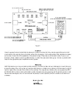
The SMEA-1P interface box is designed to be located any place along the IP camera CAT5 cable run. It must be located
in between the IP camera and the router or switcher as shown in figure 1.
NOTES-
1. The IP camera MUST be connected or the SMEA-1P will not power up.
2. The SMEA-1P will not work with non-PoE IP cameras.
Cable Run
Run a 22 gauge, stranded, two conductor shielded cable between the SMEA-1P interface and the PM1 microphone. Keep
the cable run distance under 300 feet and away from AC power sources, light fixtures and electrical equipment.
See
Figure 1 for connection diagram.
Mounting
The PM1 can be surface or flush mounted on ceilings or walls. For flush mounting, cut a 2 ¼” by 2
¾
“ hole in the wall or
ceiling tile to allow room for the circuit board and mount the PM1 to the surface with screws.
SMEA-1P Mode switch:
The SMEA-1P supports Both Modes A and B of IEEE802.3af POE. The
SMEA-1P is pre-set for the most common use of the “end point” POE IEEE802.3af standard (mode A). If the power LED
does not illuminate in this position, try the mode B position (mid span).
SMEA-1P Gain Adjustment
This control sets the gain on the pre-amplifier. For ETS PM1 series microphones and electret powered Professional
microphones a mid-range setting should be adequate. For dynamic microphones, the control may have to be set more
clockwise, since this type of microphone is less sensitive than a powered, electret type microphone.
SMEA-1P Level Adjustment
This control sets the volume of signal at the audio output jack. If your camera features a ‘line level’ audio input, start with
this control mid-ranged. If the volume is too loud or distorted, turn it down or if to faint, turn it clockwise. If your camera
features a ‘microphone input’ turn this control nearly all the way down. Then, use the gain control for best results.
Setting the SMEQ-1 Equalizer levels
Setting an equalizer for the desired overall sound is a subjective topic. Experimenting with the controls is the best way to
learn and achieve good results. We recommend using headphones to evaluate the sound quality. Start with setting all
controls to the mid-point (flat= no gain or cut). We suggest you do this when the desired sound source is present (people
taking, being interviewed, etc.) Adjust each control clockwise and counter clockwise to get a feel for how each band
affects the overall sound. Keep in mind that the human voice resides in the 1Khz-6Khz range. To focus on this band the
Bass and Treble controls can all be turned down (more counter clockwise). The Middle control can then be adjusted more
clockwise or for best sound clarity and intelligibility.


