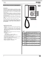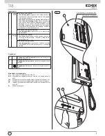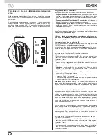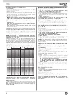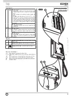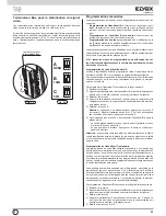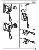
To program the secondary ID, proceed as follows:
1) Lift the handset.
2) Press buttons
B
and
A
simultaneously and hold them down until LED B
(ringtone mute) begins flashing.
3) Release the buttons.
4) Press buttons
A
and
C
simultaneously and hold them down (for 2 sec.)
until the handset emits an audible signal and communication between
the monitor and the outdoor entrance panel begins.
5) Release buttons
A
and
C
.
Important:
you will have 5 s in which to press buttons A and C (as indi
-
cated in step 4). If buttons A and C are not pressed within the 5 s, steps
1, 2 and 3 must be repeated.
6) You now have approx 30 seconds to assign the ID code of the external
entrance panel:
- in the case of an alphanumeric panel, key in the primary ID and press
the “bell” button to confirm.
- in the case of a push-button entrance panel, press the button you want
to use to call the monitor.
Important:
When programming the primary and secondary ID, the monitors
undergoing programming automatically acquire a code that depends on the
association with the button or code used to call the outdoor entrance panel.
Correspondence between the primary ID and the respective secondary ID
codes is provided in the table below.
Example:
If ID = 8 is given to a second interphone/monitor, the automatic
second interphone/monitor identification attribution procedure will automa-
tically assume ID = 72 (see table).
When a call is made to ID = 8, both monitors/interphones will chime and
both can be used to answer. If, on the other hand, in the case of an alphanu
-
meric panel you enter 72 (the ID automatically assigned by the procedure),
a chime is emitted by the interphone/monitor for which the secondary ID
assignation procedure was carried out and only this interphone can be used
to answer the call.
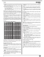
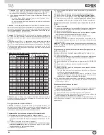
Table of primary and corresponding secondary ID codes:
ID
Primario
ID Secondario
1
2
3
1
51
52
53
2
54
55
56
3
57
58
59
4
60
61
62
5
63
64
65
6
66
67
68
7
69
70
71
8
72
73
74
9
75
76
77
10
78
79
80
11
81
82
83
12
84
85
86
13
87
88
89
14
90
91
92
15
93
94
95
16
96
97
98
17
99
100
101
18
102
103
104
19
105
106
107
20
108
109
110
21
111
112
113
22
114
115
116
23
117
118
119
24
120
121
122
25
123
124
125
ID
Primario
ID Secondario
1
2
3
26
126
127
128
27
129
130
131
28
132
133
134
29
135
136
137
30
138
139
140
31
141
142
143
32
144
145
146
33
147
148
149
34
150
151
152
35
153
154
155
36
156
157
158
37
159
160
161
38
162
163
164
39
165
166
167
40
168
169
170
41
171
172
173
42
174
175
176
43
177
178
179
44
180
181
182
45
183
184
185
46
186
187
188
47
189
190
191
48
192
193
194
49
195
196
197
50
198
199
200
Important:
to delete from a group, the programming deletion procedure de-
scribed in the “Default data restore procedure” section must be performed.
Button programming
Important: without SaveProg software, the only functions that can be as
-
signed are intercommunication, specific entrance panel self-activation, re-
storing buttons programmed by the installer to their default settings and
restoring default data.
Button programming procedure for intercommunicating calls
To program the buttons, proceed as follows:
1) Press the “talk/listen” button or lift the handset (depending on model
installed) for the
interphone/monitor TO BE CALLED
.
2) Lift the handset to be programmed (the caller handset).
3) Press buttons
B
and
A
on the monitor to be programmed (caller) si-
multaneously and hold them down until LED B (ringtone mute) begins
flashing.
4) Release buttons
B
and
A
.
5) Press and hold down the button to be programmed (e.g.
E1, E2, E3, E4
).
6) Wait until the monitor handset emits a continuous tone.
7) Release the button to be programmed
on the caller monitor
.
8) Press a button (lock/F1/F2) on the
interphone/monitor to be called
.
9) An audible signal in the handset of the
(caller) monitor being program-
med
confirms that the procedure has been completed correctly.
Procedure for restoring default data for each individual button
(E1, E2, E3, E4)
1) Lift the handset.
2) Press buttons
B
and
A
simultaneously and hold them down until LED
B
(ringtone mute) begins flashing.
3) Release buttons
B
and
A
.
4) Press and hold down the button you want to return to default program-
ming (not valid for Self-start and Lock buttons).
5) Wait until the monitor handset emits an audible signal.
6) Release the button.
7) Press the button again to confirm. The monitor handset will again emit
a signal. The button has now been restored to its default value.
Important:
This procedure can be used to manually reprogram all buttons
with the exception of the lock and self-start buttons, for which SaveProg
software is required.
Programming the self-activation/self-start button to a specific
pane
l
(different from the self-start function enabled using button “A”)
1) Lift the handset.
2) Press buttons B and A simultaneously and hold them down until LED B
(ringtone mute) begins flashing.
3) Release buttons B and A.
4) Press and hold down the button to be programmed (D, E1, E2, E3, E4).
5) Wait until the monitor handset emits a tone.
6) Release the button.
7) Call the monitor from the panel you want to perform direct self-start
from:
- On push-button entrance panels, press the button corresponding to
the monitor on which the button is being saved.
- On alphanumeric panels, enter the ID corresponding to the monitor
on which the button is being saved and press the bell button on the
panel to confirm.
8) At the end of the procedure described above, the monitor handset emits
an audible signal to indicate that the procedure has been completed
correctly.
Default data restore procedure
1) Lift the handset.
2) Press buttons
B
and
A
simultaneously and hold them down until LED B
(ringtone mute) begins flashing.
3) Release buttons
B
and
A
.
4) Press and hold down button
A
again.
5) While the monitor handset is emitting an audible signal, release button
A
and press button
C
briefly.
The monitor programming has now been deleted. To check that program-
ming has been deleted, press button
C
; the monitor handset should emit
an audible signal.
GB
16
Summary of Contents for 7529
Page 6: ...Fig 6 2 1 1 2 E E 12V CH FP M 2 1 1 2 E E 12V CH FP M Fig 7 Fig 5 I 6 ...
Page 14: ...Fig 6 2 1 1 2 E E 12V CH FP M 2 1 1 2 E E 12V CH FP M Fig 7 Fig 5 GB 14 ...
Page 22: ...Fig 6 2 1 1 2 E E 12V CH FP M 2 1 1 2 E E 12V CH FP M Fig 7 Fig 5 F 22 ...
Page 30: ...Abb 6 2 1 1 2 E E 12V CH FP M 2 1 1 2 E E 12V CH FP M Abb 7 Abb 5 D 30 ...
Page 38: ...Fig 6 2 1 1 2 E E 12V CH FP M 2 1 1 2 E E 12V CH FP M Fig 7 Fig 5 E 38 ...
Page 46: ...Fig 6 2 1 1 2 E E 12V CH FP M 2 1 1 2 E E 12V CH FP M Fig 7 Fig 5 P 46 ...

