Operating Instructions MODULAR SAFETY CONTROL SYSTEM MSC
MSC FIELDBUS MODULES CE-...
24
(Translation of the original operating instructions) 2121341-06-11/20
8. “Bus Configurator” user interface
The bus module is configured via the USB Mini-B port on the front panel and the installed “BUS CONFIGURATOR” software
(included on the CD-ROM “EUCHNER Safety Designer”).
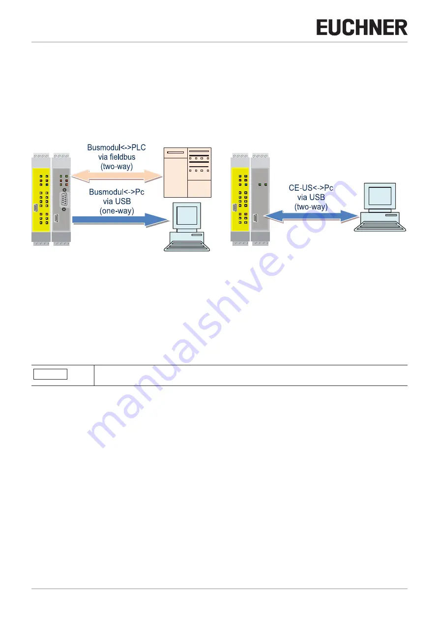
This software supports the configuration/communication of the MSC system with a PC (via a module CE-US) as well as the
indication of the data transmitted via the bus (via the connection of a bus module to the USB port).
The diagram below is used to clarify the possible connections:
CONNECTION EXAMPLES
ON RUN
EUCHNER
IN
EXT
COM ENA
FAIL
1
2
3
4
5
MSC-CB
6
7
8
1
2
1
2
1
2
OSSD
CLEAR
IN
STATUS
MSC
EUCHNER
CE-US
MSC
CONNECT
ON RUN
EUCHNER
IN
EXT
COM ENA
FAIL
1
2
3
4
5
MSC-CB
6
7
8
1
2
1
2
1
2
OSSD
CLEAR
IN
STATUS
MSC
ON
IN
EXT
RUN
EUCHNER
FAIL
CE-PR
MSC
OPR ERR
MSC-CB bus module
MSC-CB CE-US (USB)
Figure 11: Connection examples
It is to be noted that the behavior of BUS CONFIGURATOR changes depending on whether the communication is with a bus
module or a module CE-US:
Ì
BUS MODULE: THE SOFTWARE SUPPORTS ONLY THE INDICATION OF THE DATA TRANSMITTED VIA THE BUS.
Ì
MODULE CE-US: THE SOFTWARE SUPPORTS THE TWO-WAY DATA TRANSMISSION CE-US
PC
(in this case, the programmer can set the fieldbus input directly via the computer).
The parameters to be configured include the address of the module in the fieldbus network, and possibly the data transfer
speed.
FW < 2.0
Additionally, the data sets transferring the parameters, the modular I/Os and the fieldbus input can
be set.
The address space range is dependent on the type of fieldbus installed.


