27
2121341-06-11/20 (Translation of the original operating instructions)
Operating Instructions MODULAR SAFETY CONTROL SYSTEM MSC
MSC FIELDBUS MODULES CE-...
EN
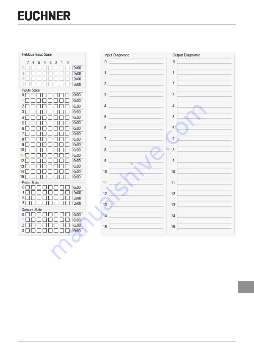
As soon as the fieldbus module receives the data, the Configurator changes to state monitoring. The status of the inputs
and outputs and the diagnoses are shown in Figure 14 and Figure 15. The first 16 diagnoses are displayed. If more than 16
diagnoses are available, the additional diagnoses are displayed after the preceding ones are deleted.
Figure 14: Input/output status
Figure 15: Input/output diagnostics
The fieldbus input, with a logical status that can be changed as required by the programmer (only for the module CE-US) or
via the fieldbus, is indicated in the upper section of Figure 14.


