Operating Instructions
Electronic-Key-System EKS2
10
(translation of the original operating instructions) 2546099-01-10/21
9.3.
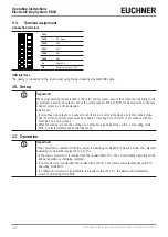
Terminal assignment
Connection terminal
FO1F
-
FO1E
MO Service
FO1D
MO4
FO1C
MO3
FO1B
MO2
FO1A
MO1
0V
Ground 0 V
UB
Operating voltage 24 V DC
USB interface
The device is connected to the touch panel using the permanently mounted USB cable.
10. Setup
Important!
When programming the evaluation in the safe control system, ensure that, when the operating mode
is selected, exactly one output is set at the safety outputs FO1A to FO1F for transmission to the safe
control system via 1-of-n evaluation.
This means:
Ì
If more than one output or no output is set, there is an error in the device or in the cable installa-
tion. The safe control system must be capable of reacting to such errors in accordance with the
machine’s risk assessment.
Ì
When the device is reset, the setting of an output can be delayed by up to 5 s. Operating mode
MO1 is selected automatically after the reset.
11. Operation
Important!
If the smartcard is removed from the reader in operating mode MO4 or Service mode, the selected
operating mode will be retained for up to 15 s:
Ì
If the same smartcard is re-inserted into the reader within 15 s, the corresponding operating mode
will be regarded as still being selected.
Ì
If no smartcard is inserted into the reader within the 15 s, the device will automatically switch to
operating mode MO1.
Ì
If a different smartcard is inserted into the reader within the 15 s, the device will immediately
switch to operating mode MO1.


