User Information
2
EUCHNER GmbH + Co. KG Kohlhammerstraße 16 D-70771 Leinfelden-Echterdingen Tel. +49/711/75 97-0 Fax +49/711/75 33 16 www.euchner.de info@euchner.de
2-Hand Safety Relay, Series ESM-2H2..
V1.1.0
ESM-2H2..
The arrangement of the two-hand buttons must be designed in accordance with the standard EN 574 such that accidental
actuation or simple bypassing of the safety function is excluded.
The ESM-2H2.. unit is provided for the connection of 2-hand push-buttons, with one normally open or one normally colsed
contact.
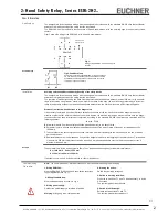
Figur 1 shows the wiring of the ESM-2H2.. with a 2-hand push-buttons:
Applications
Fig. 1:
Wiring of the ESM-2H2.. with a 2-hand push
-buttons
Fig. 2: Feedback loop
Contactors connected to the ESM-2H2.. or the basic devices
are monitored via the feedback loop of the basic device. K
A
and K
B
are the positively driven contacts of the connected
contactor or expansion module.
Feedback loop
Note: The items listed under “Electrical connection” must be observed during commissioning.
Commissioning
Procedure
1. Wiring ESM-2H2..:
Wire the ESM-2H2.. With the 2-hand push button according
to your application (see Fig. 1).
2. Wiring feedback loop:
Wire the feedback loop as shown in Fig. 2.
3. Wiring power supply:
Connect the power supply to terminals A1 and A2.
Warning: Wiring only in de-energized state.
4. Starting the device:
Switch the operating voltage on.
5. Switch to working condition:
Press the two buttons T1 and T2 simultaneously, or within
0.5 seconds.
The positive-guided relay switches.
6. Switch into hibernation:
Release the two buttons T1 and T2.
The positive-guided relay swiches off.
Jumper X1-X2:
See description
X1
X2
Installation
Avoiding unintentional actuation or bypassing of the safety device
The arrangement of the two-hand buttons must be designed in accordance with the standard EN 574 such that accidental
actuation or simple bypassing of the safety function is excluded.
The operation of both buttons using one hand must be prevented by an adequate distance (at least 260 mm) or by a separa-
ting wall. Actuation using forearm, elbow, knee, hip or other parts of the body can be effectively prevented by a further inc-
rease in the distance between the two buttons, adequate distance from the floor and/or covers and/or separating walls.
Distance from the two-hand buttons to the danger area
It is necessary to maintain a minimum distance between the buttons for the two-hand circuit and the danger area on the
machine or plant so that, after the release of one or both buttons, the machine or plant can only be reached once the dange-
rous movement has been interrupted or completed. According to the standard EN 999, the distance is calculated with the
following equation:
S = (K · T) + C
S: Minimum distance from the nearest pushbutton (two-hand button) to the danger area.
K: Parameter in mm/s, derived from data on the approach speeds of the body or parts of the body, for two-hand circuits
1600 mm/s.
T: The overtravel of the overall system in seconds, that is the time from releasing the two-hand button to the end of the dan
gerous movement.
C: Additional distance in mm that based on entry into the danger area prior to the triggering of the safety device. For twohand
circuits this is 250 mm, this distance can also be set to 0 mm given an adequate cover on the buttons, however then S
must be at least 100 mm.
Example
The overtravel time for the entire system is 90ms. Then the above equation gives for the minimum distance:
S = (1600 mm/s · 0.09 s) + 250 mm
S = 144 mm + 250 mm = 394 mm
If a suitable cover is used, S can be reduced to 144mm (see above).


