background image

System Manual Safety System MGB-AR in Combination with a Locking Module

17

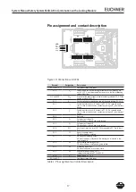
Pin assignment and contact description

Figure 16: Connections and LEDs

Terminal

Designation

Description

X.1 to X.

-

See the enclosed data sheet

X.4

U

A

Power supply for the interlocking solenoid and the monitoring out-

puts, DC 4 V, must be present continuously so that the interlocking 

solenoid functions.

X.5 and X.6

0V

M

Ground for the power supply to the interlocking solenoid, DC 0 V (con-

nected internally to X5.5).

X.7

U

CM

Control voltage for switching on and off the guard locking, DC 4 V.

X4.1

I

A

Enable input for channel A, connect to DC 4 V in separate opera-

tion. In case of switch chains, connect output signal O

A

 from previous 

device.

X4.

I

B

Enable input for channel B, connect to DC 4 V in separate opera-

tion. In case of switch chains, connect output signal O

B

 from previous 

device.

X4.

-

Not used

X4.4

O

A

Safety output channel A,

ON when door is closed and guard locked.

X4.5

O

B

Safety output channel B,

ON when door is closed and guard locked.

X4.6

RST

Reset input, device is reset if DC 4 V are applied to RST for at least 

 s.

X5.1

O1

Door monitoring output, 

ON when the door is closed.

X5.

O

Bolt tongue monitoring output,

ON when the door is closed and the bolt tongue is inserted in the 

locking module.

X5.

O

Guard locking monitoring output, 

ON when the door is closed and guard locked.

X5.4

O4

Monitoring output DIA,

ON when the device is in the fault state.

X5.5

0V

Ground for power supply, DC 0 V 

(connected internally to X.5 and X.6).

X5.6

U

B

Power supply, DC 4 V

X.1 to X.7

-

See the enclosed data sheet

Table 1: Pin assignment and contact description

4

2

6

3

5

1

1

1

4

2

6

3

5

1

2

3

4

5

X3

X4

X5

X2

LED

DIA 1

Power

DIA 2

State

gn

gn

rd

ye

7 6

2

3

4

5

7 6

Summary of Contents for MGB-AR Series

Page 1: ...More than safety System Manual Safety System MGB AR in combination with a locking module MGB L1 AR MGB L2 AR ...

Page 2: ...ors Hinged on the Left 12 Protection Against Environmental Effects 13 Electrical Connection 14 Safety in case of faults 15 Fuse protection for power supply 15 Requirements for connection cables 15 Notes on cable laying 16 Pin assignment and contact description 17 Operation as separate device 18 Operation in a CES AR switch chain 19 Information on operation in a CES AR switch chain 20 Setup 21 Teac...

Page 3: ...ry Risk assessment Principles Correct use includes compliance with the relevant requirements for installation and operation in particular EN ISO 13489 1 Safety of machinery Safety related parts of control systems General principles for design EN 1088 Safety of machinery Interlocking devices associated with guards Principles for design and selection EN 60204 1 Safety of machinery Electrical equipme...

Page 4: ...tion of the safety guard particularly after any setup work after the replacement of an MGB component after an extended period without use after every fault Independent of these checks the safe function of the safety guard should be checked at suitable intervals as part of the maintenance schedule Warning Loss of safety function in the event of incorrect connection or incorrect use Safety switches ...

Page 5: ...oth safety inputs IA and IB must be on The locking module detects the position of the safety guard and the position of the bolt tongue The position of the locking arm is also monitored The bolt tongue in the handle module is retracted and extended by actuating the door handle When the bolt tongue is fully inserted in the locking module the locking arm locks the bolt tongue in this position Dependi...

Page 6: ... mounting distance 6 Depending on version Cable entry M20x1 5 or plug con nector Note Depending on the version additional controls and indicators may be integrated into the cover and a mounting plate can be included See enclosed data sheet 1 2 3 4 Key 1 Door handle 2 Locking pins for housing cover and handle adjustment 3 Lockout bar 4 Bolt tongue Note Depending on the version a mounting plate can ...

Page 7: ...n drawing Figure 4 Dimension drawing MGB fitted without optionial mounting plates y x z 51 72 114 40 40 93 113 5 110 M20x1 5 4x 19 2 289 3 AUF OPEN CLOSED ZU 40 130 15 111 40 4 155 3 40 10 58 5 110 8 x 8 7 5 6 5 86 5 15 4 15 73 5 6 3 6 2 8 9 4 24 5 10 4 6 10 8 9 4 7 7 5 9 2 5 16 5 ...

Page 8: ... and sealed after use for example with sealing lacquer Tightening torque 0 5 Nm Undo locking screws Lift locking arm using a screwdriver and actuate door handle Important The system enters into a latching fault when the mechanical release is actuated See system status table on page 23 state signal sequence erroneous DIA1 flashes six times Note The system might not enter into a latching fault if th...

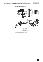
Page 9: ...andle module In case of profile widths larger than 40 mm and on the usage of mounting plates use 250 mm actuation axis order no 106 761 and cut to length In case of profile widths smaller than 40 mm cut actuation axis and protective sleeve to length Align escape release axis at right angles to the handle module See Figures 4 and 8 Install escape release so that operation as well as inspection and ...

Page 10: ...t actuation axis The locking ring A must be in contact with the escape release B 3 Tighten setscrew to 2 Nm 4 Fit protective sleeve Figure 7 Preparing the escape release 1 3 2 4 A B Protective sleeve Actuation axis Example with mounting plates 58 5 4 D 4 10 55 5 4 mm per plate 250 182 Mounting plates D 13 5 3 5 4 mm per plate D 3 ...

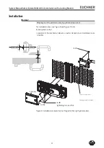
Page 11: ...nel For installation steps see Figure 8 and Figure 9 to 14 Install system so that operation of the mechanical release as well as inspection and maintenance are possible Figure 8 Installation example for door hinged on the right general view 4x M6 2x M6 0 5 Nm 1 Nm 6x Fastening material not included Cut out for escape release Tightening torque 4 Nm ...

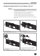
Page 12: ...Figure 9 For this reason the actuating direction of the door handle must be changed see Figure 9 14 CLOSED OPEN 1 3 2 4 5 4 Lift locking pin on the door handle using a screwdriver and hold in this position 5 Turn door handle to right 1 Push door handle upwards 2 Unscrew locking pins to the marking 3 Push cover to the side 7 a 6 b 4 mm 8 6 Only on the usage of an escape release Turn joint with hex ...

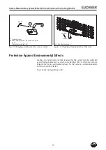
Page 13: ...ng actuating direction step 9 and AT Figure 14 Changing actuating direction final state Protection Against Environmental Effects Lasting and correct safety function requires that the system must be protected against foreign bodies such as swarf sand blasting shot etc which can become lodged in the locking and handle modules For this purpose a suitable installation position should be selected Cover...

Page 14: ...ault or by other equivalent isolation measures For use and operation as per the requirements a power supply with the feature for use in class 2 circuits must be used The same requirement ap plies to the safety outputs Alternative solutions must comply with the following requirements a Electrically isolated power supply unit with a max open circuit voltage of 30 V DC and a limited current of max 8 ...

Page 15: ...outputs O1 O4 4 x max 200 mA sole noid control elements IOA OB Load current of safety outputs OA OB 2 x max 200 mA Max current consumption of a switch chain Σ Imax Σ Imax IOA OB n x IUB IUA n Number of devices connected Assignment of the currents to the fuse circuits Current Fuse circuit F1 Fuse circuit F2 IUB 80 mA IOA OB 2 x max 200 mA IUA ISolenoid 350 mA IO1 O4 4 x max 200 mA IControl elements...

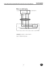
Page 16: ...bination with a Locking Module 16 Notes on cable laying Lay all MGB connection cables in a common cable harness Important lay cables in a common harness Figure 15 Stipulate cable laying PLC 24 V DC cabinet 0 V MGB L AR IA IB OA OB UB 0V UA 0V ...

Page 17: ...V in separate opera tion In case of switch chains connect output signal OB from previous device X4 3 Not used X4 4 OA Safety output channel A ON when door is closed and guard locked X4 5 OB Safety output channel B ON when door is closed and guard locked X4 6 RST Reset input device is reset if DC 24 V are applied to RST for at least 3 s X5 1 O1 Door monitoring output ON when the door is closed X5 2...

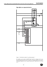
Page 18: ... RST input for at least 3 seconds The supply voltage to the switches is interrupted during this time The RST input must be connected to 0 V if it is not used 24V GND F1 X5 6 UB X5 5 0V X5 4 OUT4 X5 3 OUT3 X5 2 OUT2 X5 1 OUT1 X4 6 RST MGBL X4 5 OB X4 4 OA X4 3 X4 2 IB X4 1 IA Entriegeln Unlock X3 7 UCM X3 6 0VM X3 5 0VM F2 X3 4 UA A1 24VDC A1 A2 S11 S10 ESM BA3xx S13 EUCHNER Start KA KB S21 S12 K1 ...

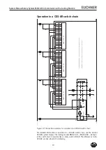
Page 19: ... A2 S11 S10 ESM BA3xx S13 EUCHNER S21 S12 K1 UB X5 6 0V X5 5 O4 X5 4 S14 K2 O3 X5 3 O2 X5 2 O1 X5 1 F5 13 14 K5 RST X4 6 OB X4 5 MGB L1 AR 3 OA X4 4 F6 23 24 K6 NC X4 3 IB X4 2 IA X4 1 33 34 UCM X3 7 NC X3 6 41 42 0VM X3 5 F2 UA X3 4 UB X5 6 0V X5 5 O4 X5 4 O3 X5 3 O2 X5 2 O1 X5 1 RST X4 6 OB X4 5 MGB L1 AR 2 OA X4 4 NC X4 3 IB X4 2 IA X4 1 UCM X3 7 NC X3 6 0VM X3 5 F3 ACHTUNG Rückführkreis muss e...

Page 20: ...lay cables in a common harness Figure 19 Position in a CES AR switch chain Output current The safety outputs on the guard locking module have a lower maximum output current than a CES AR switch see Technical data Number of devices in the switch chains In a pure MGB switch chain a maximum of ten devices can be connected in series In mixed switch chains e g together with CES AR the maximum number of...

Page 21: ...ance using the mark ing on the locking module and re adjust if necessary Insert bolt tongue in the locking module Apply operating voltage to the locking module The green LED DIA1 flashes quickly approx 10 Hz A self test is performed during this time approx 8 s After this the LED flashes cyclically three times and signals that it is in standby state for teach in Standby state for teach in remains a...

Page 22: ...guard locking by solenoid force activate guard locking The machine must not start automatically It must not be possible to open the safety guard The green STATE LED lights up continuously Enable operation in the control system It must not be possible to deactivate guard locking as long as operation is enabled Disable operation in the control system and deactivate guard locking The safety guard mus...

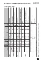
Page 23: ...er up Setup closed inserted on off off on on off 2 Hz Teach in operation X X X off off off off off 1 Hz Positive acknowledgement after completion of teach in operation Fault display X X X off off off off on 2 x Input fault e g missing test pulses illogical switch state from next switch X X X off off off off on 3 x Handle module read error e g fault in code or code not readable X X X off off off of...

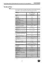
Page 24: ...ion IUB no load on any outputs 80 mA Current draw with interlocking solenoid IUA with energized interlocking solenoid and unloaded outputs O1 O4 350 mA Additional current consumption for version with controls and indicators in the cover Max 20 mA External fuse See page 16 Fuse protection for power supply Safety outputs OA OB Semiconductor outputs p switching short circuit proof Output voltage UOA ...

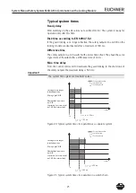
Page 25: ... to deactivate the guard locking to the shut down of the safety outputs the maximum delay is 500 ms Important The system times given are maximum values Figure 20 Typical system times for operation as a separate system Figure 21 Typical system times for operation in a switch chain t0 t0 150 ms toff t0 300 ms toff t ms t0 toff Short circuit or cross circuit on OA OB or internal fault Missing signal ...

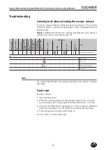
Page 26: ...s Open the safety guard Switch the operating voltage off at the locking module for min 3 seconds As an alternative 24 V can be applied to the input RST for min 3 seconds The green LED DIA1 flashes quickly approx 10 Hz A self test is performed during this time approx 8 s The LED then cyclically flashes three times Close safety guard and switch guard locking on The system is in normal mode again 1 G...

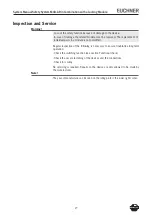
Page 27: ...al parts in a module is not permitted Regular inspection of the following is necessary to ensure trouble free long term operation Check the switching function see section Functional check Check the secure fastening of the devices and the connections Check for soiling No servicing is required Repairs to the device are only allowed to be made by the manufacturer Note The year of manufacture can be s...

Page 28: ...System Manual Safety System MGB AR in Combination with a Locking Module 28 Declaration of Conformity ...

Page 29: ...System Manual Safety System MGB AR in Combination with a Locking Module 29 ...

Page 30: ...www euchner de Issue 105995 05 12 10 Title System Manual Safety System MGB AR in Combination with a Locking Module translation of the original operating instruc tions Copyright EUCHNER GmbH Co KG 12 2010 Subject to technical modifications no responsibility is accepted for the accuracy of this information ...

Reviews: