13
2123622-04-06/19 (translation of the original operating instructions)
Operating Instructions Safety Systems
MGB-L..B-PN.-… (PROFINET) and With Expanded Data Structure Type C
EN
7.8.
Lockout mechanism
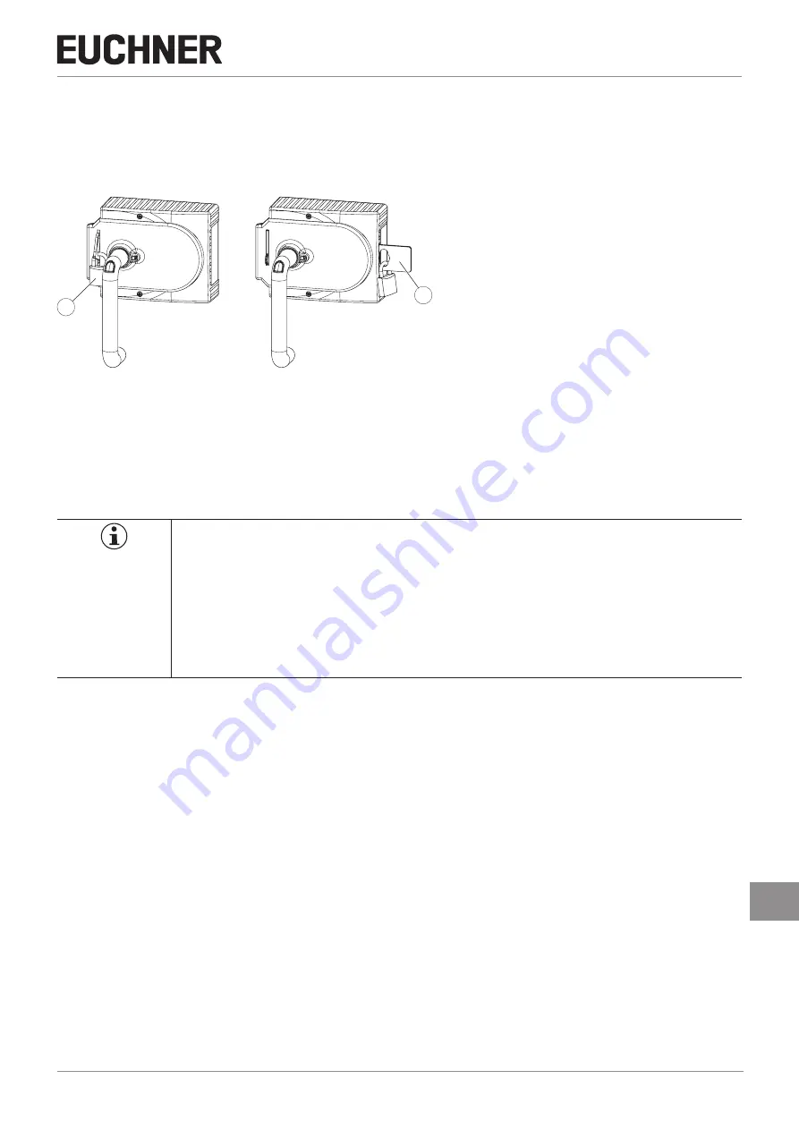
If the lockout mechanism is pivoted out/extended, the bolt tongue cannot be extended. The lockout mechanism can be
¨
To pivot out, press the grooved part (only possible with bolt tongue retracted).
1
2
Key
:
1
Padlock
∅
min. 2 mm,
∅
max. 10 mm
Notice:
You can fit a maximum of 3 locks Ø 8 mm
.
2
Automatically extending, second lockout mechanism
Padlock
∅
min. 6 mm,
∅
max. 10 mm
Figure 7:
Lockout mechanism secured with padlock
7.9.
Escape release (optional)
The escape release is used to open a locked safety guard from the inside without tools.
The system enters into a latching fault when the escape release is actuated.
15. System status table on page 38
,
signal sequence incorrect
status (DIA red, Lock flashes 1 time).
The system might not enter into a latching fault if the escape release is actuated very slowly.
Important!
Ì
It must be possible to operate the escape release manually from inside the protected area without
tools.
Ì
It must not be possible to reach the escape release from the outside.
Ì
The actuator must not be under tensile stress during manual release.
Ì
The escape release meets the requirements of Category B according to EN ISO 13849-1:2008.
Ì
The correct function must be checked at regular intervals.
Ì
Please observe the notes on possibly enclosed data sheets.
Ì
Fit escape release such that operation, inspection and service are possible.
Ì
The actuation axis for the escape release must be inserted min. 10 mm into the handle module. Note the information on
the different profile widths in the next chapter.
Ì
Align escape release axis at right angles to the handle module. See


