33
2123622-04-06/19 (translation of the original operating instructions)
Operating Instructions Safety Systems
MGB-L..B-PN.-… (PROFINET) and With Expanded Data Structure Type C
EN
13.9.3. “Expanded” PROFIsafe data bytes
The “expanded” PROFIsafe data block includes all safe functions. It is subdivided as follows:
Ì
2 input bytes of data for the functions (e.g. emergency stop switch position)
Ì
2 additional input bits (empty)
Ì
4 input bytes used within PROFIsafe
Ì
1 output byte for the functions (e.g. safe control of guard locking)
Ì
1 additional output byte (empty)
Ì
4 output bytes used within PROFIsafe
All data bits are present in parallel in the non-safety-related PROFINET and can be used as signaling bits there.
Important!
Never use the signaling bits for safety functions.
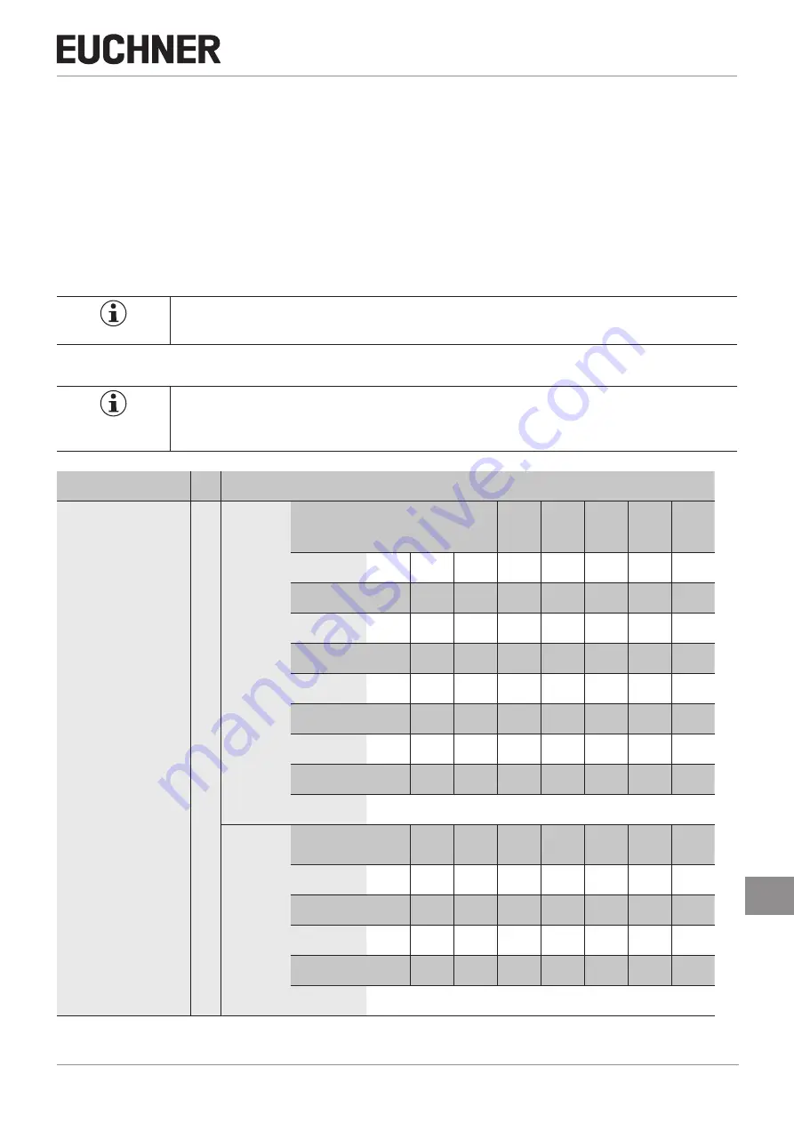
13.9.4. Data block for “expanded” PROFIsafe
Important!
Ì
Refer to the data sheet enclosed with your MGB system for the exact bit allocation. Use only bits
that are specified according to the data sheet.
Function
Slot
Required memory in data range of the control system (IO controller)
(see below for exact bit allocation)
Diagnostics
See data sheet for slot assignment
Input range
(8 bytes)
Function
-
Guard
locking
(Z)
Bolt
position
(R)
Door
position
(T)
ES (en-
abling
switch)
S94
emer-
gency
stop
1st byte
SI0.7
SI0.6
SI0.5
SI0.4
SI0.3
SI0.2
SI0.1
SI0.0
Function
-
-
-
-
-
-
ÜK
SK
2nd byte
SI1.7
SI1.6
SI1.5
SI1.4
SI1.3
SI1.2
SI1.1
SI1.0
Function
PSÜK
-
-
ZSIN
ZSQ
ÜKQ
SKQ
NHQ
3rd byte
SI2.7
SI2.6
SI2.5
SI2.4
SI2.3
SI2.2
SI2.1
SI2.0
Function
-
-
-
-
-
-
-
-
4th byte
SI3.7
SI3.6
SI3.5
SI3.4
SI3.3
SI3.2
SI3.1
Function
5th - 8th bytes
Used within PROFIsafe (control byte, CRC, etc.)
Output range
(6 bytes)
Function
ETR
ENR
ANH
-
-
-
Emer-
gency
release
Guard
locking
1st byte
SO0.7
SO0.6
SO0.5
SO0.4
SO0.3
SO0.2
SO0.1
SO0.0
Function
-
-
-
-
-
-
-
-
2nd byte
SO1.7
SO1.6
SO1.5
SO1.4
SO1.3
SO1.2
SO1.1
SO1.0
Function
3rd - 6th bytes
Used within PROFIsafe (control byte, CRC, etc.)


