Operating Instructions Safety Systems
MGB-L0…-AR.-… and MGB-L0…-AP.-…
12
(translation of the original operating instructions) 112657-12-01/15
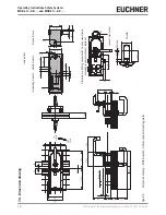
7.4.
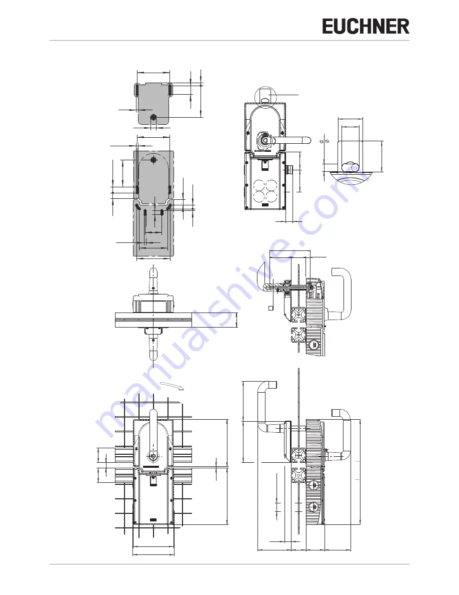
Dimension drawing
47
,5
60
19
m
in
.
6
37
,5
S1
S2
4
S
3
S
A
m
ax
.
10
30
21
51
61,5
114
40
40
83
11
3,
5
M
20
x1
,5
(4
x)
19,
2
28
9,
3
AUF
O
PE
N
CL
O
SE
D
ZU
40
130
15
111
40
4
15
5,
3
104
40
11,5
58,5
110
8 x 8
(min. 10)
7,5
6,6
86
,5
15
,4
15
73
,5
6,3
6,2
89
,4
24
5
10
46
10
89
,4
77
,5
92
,5
16
,5
14,5
Hole pattern
Interlocking module
Handle module
Escape r
elease
Detail
A
Dimensions with plug connector RC18 and automatically
extending lockout mechanism (optional)
Padlock
Lockout mechanism
Figur
e 4:
Dimension drawing – MGB mounted, without optional mounting plates


