21
112657-12-01/15 (translation of the original operating instructions)
Operating Instructions Safety Systems
MGB-L0…-AR.-… and MGB-L0…-AP.-…
EN
11. Electrical connection
WARNING
In case of an error, loss of the safety function through incorrect connection.
Ì
To ensure safety, both safety outputs (FO1A and FO1B) must always be evaluated.
Ì
The monitoring outputs must not be used as safety outputs.
Ì
Lay the connection cables with protection to prevent the risk of short circuits.
CAUTION
Risk of damage to equipment or malfunctions as a result of incorrect connection.
Ì
The inputs on an evaluation unit connected must be positive-switching, as the two outputs on the
safety switch deliver a level of +24 V in the switched-on state.
Ì
All the electrical connections must either be isolated from the mains supply by a safety trans-
former according EN IEC 61558-2-6 with limited output voltage in the event of a fault, or by other
equivalent isolation measures.
Ì
All electrical outputs must have an adequate protective circuit for inductive loads. The outputs
must be protected with a free-wheeling diode for this purpose. RC interference suppression units
must not be used.
Ì
Power devices which are a powerful source of interference must be installed in a separate location
away from the input and output circuits for signal processing. The cable routing for safety circuits
should be as far away as possible from the cables of the power circuits.
Ì
To prevent EMC problems, it is imperative you follow the chapter
11.5. Notes on cable laying on
page 23
. Follow EMC notes on devices in the immediate vicinity of the MGB system and their
cables.
Ì
In order to avoid EMC interference, the physical environmental and operating conditions at the
installation site of the device must comply with the requirements according to the standard
DIN EN 60204-1:2006, section 4.4.2/EMC.
Important!
Ì
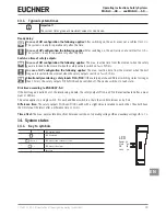
If the device does not appear to function when the operating voltage is applied (e.g. green Power
LED does not illuminate), the safety switch must be returned to the manufacturer.
Ì
To ensure the stated degree of protection is achieved, the cover screws must be tightened to a
tightening torque of 1 Nm.
Ì
Tighten screw for the cover for the mechanical release to 0.5 Nm.

