Operating Instructions Safety Systems
MGB-L0…-AR.-… and MGB-L0…-AP.-…
22
(translation of the original operating instructions) 112657-12-01/15
11.1. Notes about
Important!
Ì
For use and operation as per the
requirements
1)
, a power supply with the feature “for use in
class 2 circuits” must be used. The same requirement applies to the safety outputs.
Alternative solutions must comply with the following requirements:
a) Electrically isolated power supply unit with a max. open-circuit voltage of 30 V/DC and a limited
current of max. 8 A.
b) Electrically isolated power supply unit in combination with fuse as per UL248. This fuse should be
designed for max. 3.3 A and should be integrated into the 30 V DC voltage section.
Ì
The mounting of conduits directly on the MGB is not allowed. Cables are only allowed to be
connected via suitable cable glands. For this purpose use EUCHNER cable gland of type
EKPM20/06U. Equivalent cable glands can be used if they are UL-listed (QCRV) and are suitable
for the related cable diameter (22 AWG – 17 AWG).
1) Note on the scope of the UL approval: Only for applications as per NFPA 79 (Industrial Machinery).
The devices have been tested as per the requirements of UL508 (protection against electric shock and fire).
11.2. Safety in case of faults
Ì
The operating voltage UB is reverse polarity protected.
Ì
The safety outputs FO1A/FO1B are short circuit-proof.
Ì
A short circuit between FI1A and FI1B or FO1A and FO1B is detected by the device.
Ì
A short circuit in the cable can be excluded by laying the cable with protection.
11.3. Fuse protection for power supply
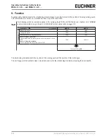
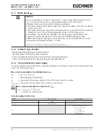
The power supply must be provided with fuse protection depending on the number of devices and current required for the
outputs. The following rules apply:
Max. current consumption of an individual device I
max
I
max
= I
UB
+ I
UA
+ I
FO1A+FO1B
I
UB
= Device operating current (80 mA)
I
UA
= Load current of monitoring outputs OD, OT and OI (3 x max. 50 mA) + switches
I
FO1A+FO1B
= Load current of safety outputs FO1A + FO1B (2 x max. 50 mA)
AR
Max. current consumption of a switch chain
Σ
I
max
Σ
I
max
= I
FO1A+FO1B
+ n x (I
UB
+ I
UA
)
n
= Number of connected devices
Current assignment to the fuses
Current
Fuse circuit F1
Fuse circuit F2
I
UB
80 mA
I
FO1A+FO1B
(2 x max. 200 mA)
I
UA
I
OD,OT,OI
= (3 x max. 50 mA)
I
switches
= max. 100 mA
(per switch)
I
indicators
= max. 5 mA
(per indicator)


