27
112657-12-01/15 (translation of the original operating instructions)
Operating Instructions Safety Systems
MGB-L0…-AR.-… and MGB-L0…-AP.-…
EN
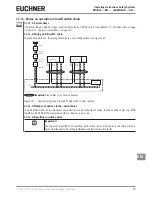
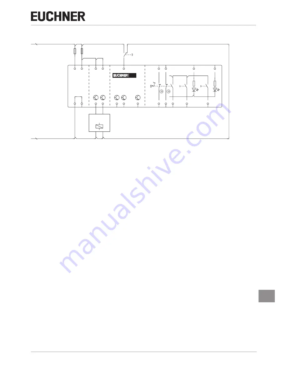
11.9. Operation as separate device
GND
Safety
Outputs
Safety
Inputs
Monitoring Outputs
X2:1
X2:6
H2
H3
S2
S3
0V
UA
S1
FI1A
X4:1
FI1B
X4:2
RST
X4:6
FO1A
X4:4
FO1B
X4:5
OD
X5:1
OT
X5:2
OI
X5:4
0V
X5:5
0V
X3:5
UA
X3:4
UB
X5:6
X3:3
X2:3
X2:4
X2:2
X2:7
X3:2
X3:1
MGB
+24 V DC
Connected
load
-F1 -F2
-S1
Figure 16: Connection example for separate operation
The switches can be reset via the RST input. To do this, a voltage of 24 V is applied to the RST input for at least 3 seconds.
The supply voltage to the switches is interrupted during this time. The RST input must be connected to 0 V if it is not used.

