29
112657-12-01/15 (translation of the original operating instructions)
Operating Instructions Safety Systems
MGB-L0…-AR.-… and MGB-L0…-AP.-…
EN
11.11. Notes on operation in an AR switch chain
AR
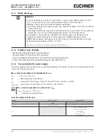
11.11.1. System times
The interlocking module has longer reaction times than a CES-AR switch (see chapters
13. Technical data on page
32
and
13.1. Typical system times on page 33
).
11.11.2. Wiring an AR switch chain
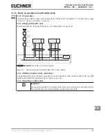
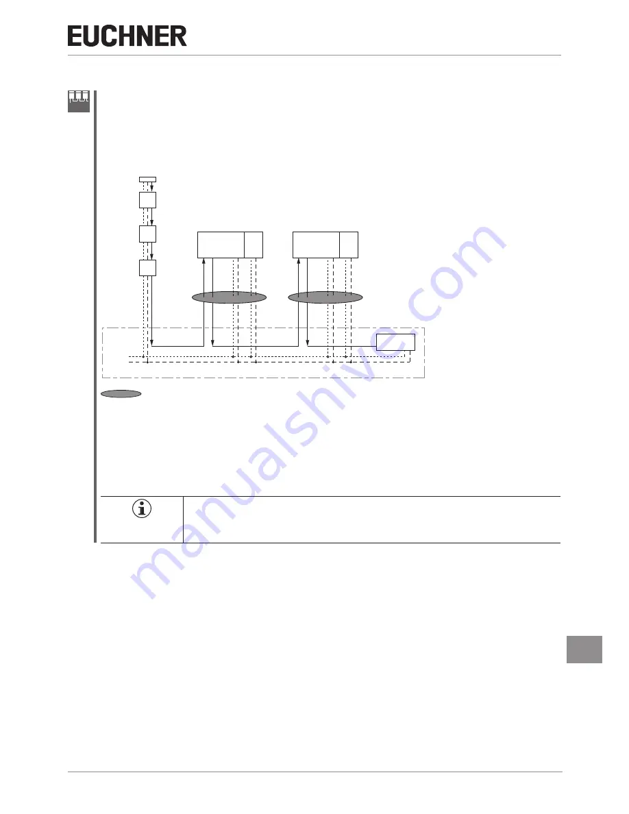
To prevent earth loops, the wiring should be in a star configuration (see
Figure 18
).
CES-AR
terminating plug
CES-AR
CES-AR
PLC
MGB-L.-AR...
+ 24 V DC
cabinet
0 V
FI1A/FI1B
FI1A/FI1B
FO1A/FO1B
FI1A/
FI1B
FO1A/
FO1B
UB 0V UA 0V
#1
#2
#3
#4
MGB-L.-AR...
#5
FI1A/FI1B
FO1A/FO1B
FI1A/
FI1B
FO1A/
FO1B
UB 0V UA 0V
FO1A/FO1B
Important
: lay cables in a common harness
Figure 18: Central wiring of an AR switch chain in the control cabinet
11.11.3. Number of devices in the switch chains
In a pure MGB switch chain a maximum of ten devices can be connected in series. In mixed switch chains (e.g. MGB
together with CES-AR) the maximum number of devices is also ten.
11.11.4. Resetting in switch chains
Important!
Use the reset input (RST) for resetting in AR switch chains. All devices in the chain must be
reset simultaneously. Resetting individual switches will result in faults.


