Operating Instructions Safety Systems
MGB2-L1…-BR.-… / MGB2-L2…-BR.-… and MGB2-L1…-BP.-… / MGB2-L2…-BP.-…
8
(Translation of the original operating instructions) 2500233-01-05/19
Important!
Ì
The user is responsible for the proper integration of the device into a safe overall system. For this
purpose, the overall system must be validated, e.g. in accordance with EN ISO 13849-2.
Ì
Correct use requires observing the permissible operating parameters (see chapter 16. Technical
Ì
If a data sheet is included with the product, the information on the data sheet applies.
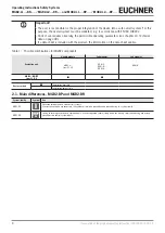
Table 1: Possible combinations for MGB2 components
Evaluation unit
Handle module
Submodules
Submodules
MGB2-H-...
from V1.0.0
MSM-.-P-...
MSM-.-N-...
MSM-.-K-...
MSM-.-R-...
MGB2…BR/BP
from V1.0.0
–
Key to symbols
Combination possible
–
Combination not possible
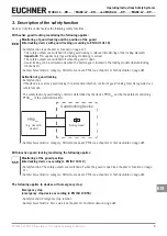
2.1. Main differences, MGB2-BP and MGB2-BR
System family
Symbol
Use
MGB2-BP
BP
Optimized for operation in safe control systems.
If series connection is not necessary, the number of terminals required can be reduced using this system family.
MGB2-BR
BR
Linking of several guards on one shutdown path. As a consequence several safety doors can be very simply polled using one evalua-
tion unit or two control system inputs.


