Operating Instructions
Modular Safety Control System MSC
120
(Translation of the original operating instructions) 2121331-04-04/19
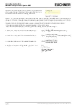
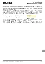
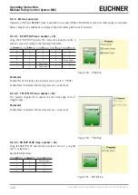
Hysteresis (%): Corresponds to the hysteresis (in percent) below
which a speed change is filtered out. Here a value other than 1 is to
be entered to prevent continuous switching of the input.
Figure 129: Hysteresis
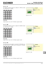
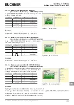
Speed 1, 2, 3, 4: Enter the highest speed in this field. If the speed is exceeded, the OVER output on the function block
changes to "0" (FALSE). If the speed measured is below the value entered, the OVER output on the function block is "1" (TRUE).
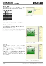
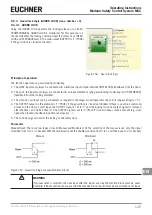
Frequency: Indicates the maximum frequency values calculated fM and fm (reduced by the hysteresis entered).
Ì
If the value indicated is GREEN, the calculated frequency is in the correct range.
Ì
If the value indicated is RED, the parameters given in the following formulas must be changed.
1. Rotary axis, rotary sensor. The calculated frequency is:
f Hz
[ ]
=
rpm rev /min
[
]
60
*
Resolution pulses/rev
[
]
2. Linear axis, rotary sensor. The calculated frequency is:
f Hz
[ ]
=
speed m/min
[
]
*
1000
60
*
pitch mm/rev
[
]
*
Resolution pulses/rev
[
]
3. Linear axis, linear sensor. The calculated frequency is:
f Hz
[ ]
=
speed mm/s
[
]
*
1000
Resolution µm/pulse
[
]
4. Hysteresis. Only to be changed if: fM = green; fm = red
KEY:
f = Frequency
rpm = Rotary speed
Resolution = Measurement
speed = Linear speed
pitch = Pitch
Summary of Contents for MSC
Page 1: ...EN Operating Instructions Installation and use Modular Safety Control System MSC ...
Page 171: ......
Page 173: ......

