127
2121331-04-04/19 (Translation of the original operating instructions)
Operating Instructions
Modular Safety Control System MSC
EN
Encoder Resolution: Entry for the number of pulses/revolution (for a rotary sensor) or μm/pulse (for a linear sensor) in
relation to the 1st measuring device.
Verification: In this field you can enter the number of pulses/revolution (for a rotary sensor) or µm/pulse (for a linear sensor)
in relation to the 2nd measuring device.
Gear Ratio: This parameter is active if there are two sensors on the selected axis. This parameter enables you to enter the
gear ratio between the two sensors. If the two sensors are on the same moving object, the ratio is 1, otherwise the figure
for the ratio must be entered. Example: There is an encoder and a proximity switch and the latter is on the moving object
that (due to a gear ratio) moves at twice the speed of the encoder. For this reason, this value must be set to 2.
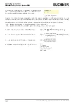
Hysteresis (%): Corresponds to the hysteresis (in percent) below
which a speed change is filtered out. Here a value other than 1 is to
be entered to prevent continuous switching of the input.
Figure 138: Hysteresis
Zero speed limit: Enter in this field the highest speed above which the function block output is ZERO "0" (FALSE). If the speed
measured is below the value entered, the ZERO output on the function block is "1" (TRUE).
Speed 1, 2, 3, 4: Enter the highest speed in this field. If the speed is exceeded, the OVER output on the function block
changes to "0" (FALSE). If the speed measured is below the value entered, the OVER output on the function block is "1" (TRUE).
Summary of Contents for MSC
Page 1: ...EN Operating Instructions Installation and use Modular Safety Control System MSC ...
Page 171: ......
Page 173: ......

