Operating Instructions
Modular Safety Control System MSC
136
(Translation of the original operating instructions) 2121331-04-04/19
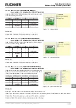
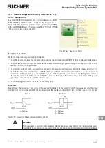
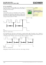
Unlock Time (s): The time that elapses between the activation of the Unlock_cmd input and the actual release of the locking.
Ì
0 ms to 1 s – 100 ms step
Ì
1.5 s to 10 s – 0.5 s step
Ì
15 s to 25 s – 5 s step
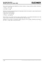
Feedback Time: Maximum time delay between the LockOut output and the Lock_fbk input (as stated in the data sheet for
the guard lock, with required delay).
Ì
10 ms to 100 s – 10 ms step size
Ì
150 ms to 1 s – 50 ms step size
Ì
1.5 s to 3 s – 0.5 s step size
Interlock Spring: The guard lock is locked passively and released actively, i.e. it is locked by the mechanical force in the
spring. The guard lock therefore remains locked after interruption of the power supply.
Enable Error Out: This option can be selected to enable a signal (Error OUT) for signaling a malfunction in the locking. If
Error OUT = "1" (TRUE), there is an error in the locking.
Summary of Contents for MSC
Page 1: ...EN Operating Instructions Installation and use Modular Safety Control System MSC ...
Page 171: ......
Page 173: ......


